Toyota Tundra Service Manual: Terminals Of Ecu

TERMINALS OF ECU

1. AIR CONDITIONING AMPLIFIER

(a) Measure the voltage and resistance according to the value(s) in the table below.

Terminal No. (Symbol)

Wiring Color

Terminal Description

Condition

Specified Condition

J106-9 (SVDB) - Body ground

R - Body ground

Output climate control signal (Driver side)

Ignition switch ON

Seat heater switch LH on

Pulse generation

(see waveform)

J106-10 (SVPB) - Body ground

BE - Body ground

Output climate control signal (Front passenger side)

Ignition switch ON

Seat heater switch RH on

Pulse generation

(see waveform)

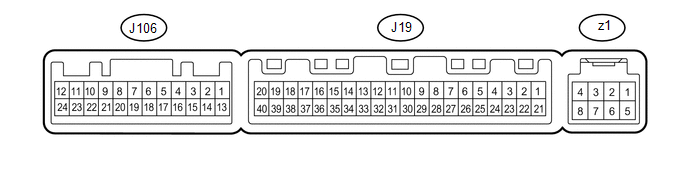
(1) Using an oscilloscope, check waveform.
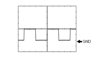
Measurement Condition

Item

Content

Terminal No. (Symbol)

J106-9 (SVDB) - Body ground

J106-10 (SVPB) - Body ground

Tool Setting

2 V/DIV., 500 μsec/DIV.

Condition

Ignition switch ON

Seat heater switch on

2. AIR CONDITIONING CONTROL ASSEMBLY (See page )

    System Diagram

    Front Power Seat Control System(w/ Memory)

    See More:

    Toyota Tundra Service Manual > Lin Communication System: P/W Master Switch Communication Stop (B1206)
    DESCRIPTION This DTC is stored when LIN communication between the power window regulator master switch assembly and main body ECU (multiplex network body ECU) stops for 10 seconds or more. DTC Code DTC Detection Condition Trouble Area B1206 No communication between the power window regulator master ...

    Toyota Tundra Owners Manual

    Toyota Tundra Service Manual

    © 2025 Copyright www.ttundra.com
    0.0092