DESCRIPTION When a signal is input into the position control ECU and switch assembly, the ECU manages the signals received from the power seat switches, and operates each motors. If the position control ECU and switch assembly receives more than 2 motors operation signals, the motor is stopped. Manual operation is restarted after the position control ECU and switch assembly receives 1 signal only. WIRING DIAGRAM 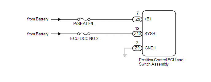
CAUTION / NOTICE / HINT NOTICE: Inspect the fuses for circuits related to this system before performing the following inspection procedure. PROCEDURE
(a) Check that each function of the power seat operates normally by using the
power seat switches (See page
(b) Measure the voltage according to the value(s) in the table below. Standard Voltage:
(c) Measure the resistance according to the value(s) in the table below. Standard Resistance:
|
Toyota Tundra Service Manual > Touch Select 2-4 And High-low System: Shift Motor Circuit
WIRING DIAGRAM CAUTION / NOTICE / HINT NOTICE: When the vehicle is stopped, mode switching may be unavailable due to the phase of the transfer assembly and A.D.D. actuator powertrain. There is no malfunction if mode switching is available after the vehicle is moved. PROCEDURE 1. CONFIRM PROBLEM SYMP ...

 ).
).