
INSPECTION PROCEDURE 1. INSPECT FRONT NO. 1 SPEAKER ASSEMBLY (for Standard) 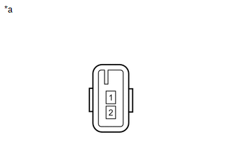 (a) Measure the resistance according to the value(s) in the table below. Standard resistance:
If the result is not as specified, replace the front No. 1 speaker assembly. Text in Illustration
2. INSPECT FRONT NO. 1 SPEAKER ASSEMBLY (for 12 Speakers) (a) Measure the resistance according to the value(s) in the table below. Standard resistance:
If the result is not as specified, replace the front No. 1 speaker assembly. Text in Illustration
3. INSPECT FRONT NO. 3 SPEAKER ASSEMBLY (for 12 Speakers) (a) When there is a malfunction such as noise from a speaker or no sound at all, replace the speaker with a new one and check that the malfunction disappears. OK: Malfunction disappears. HINT:
|
Toyota Tundra Service Manual > Vehicle Stability Control System: Error in Matching of ECUs (C1288)
DESCRIPTION The skid control ECU (brake actuator assembly) stores this DTC when the previously learned values in the VSC system and engine information sent from the ECM are inconsistent, or when the learning has not completed after the skid control ECU (brake actuator assembly) is replaced with a ne ...


