INSTALLATION CAUTION / NOTICE / HINT HINT:
PROCEDURE 1. INSTALL FRONT NO. 3 SPEAKER ASSEMBLY (for 12 Speakers)
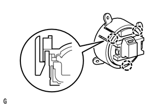
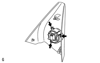
2. INSTALL FRONT NO. 1 SPEAKER ASSEMBLY (a) Connect the connector. 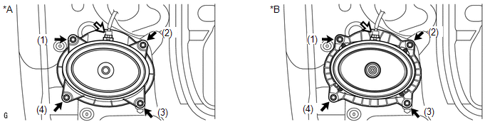 Text in Illustration Text in Illustration
(b) Install the front No. 1 speaker assembly with the 4 screws. NOTICE: Do not touch the cone part of the speaker. HINT: Install the screws in the order shown in the illustration. 3. INSTALL FRONT DOOR TRIM BOARD SUB-ASSEMBLY LH
4. INSTALL FRONT DOOR ARMREST COVER LH 5. INSTALL FRONT UPPER ARMREST BASE PANEL LH
6. INSTALL FRONT DOOR INSIDE HANDLE BEZEL PLUG LH 7. INSTALL FRONT LOWER DOOR FRAME BRACKET GARNISH LH |
Toyota Tundra Owners Manual > Multimedia: Using the voice
command system
Voice command system The voice command system enables the hands-free system to be operated using voice commands. Operations of the voice command system can be performed by selecting the menu corresponding to each function on the screen. Even if any menu is selected, commands displayed on all menus c ...