DESCRIPTION The passenger airbag ON/OFF indicator circuit consists of the airbag sensor assembly and passenger airbag ON/OFF indicator. The passenger airbag ON/OFF indicator indicates the operation condition of the lower No. 2 instrument panel airbag assembly, instrument panel passenger without door airbag assembly and front seat airbag assembly RH. DTC B1660 is stored when a malfunction is detected in the passenger airbag ON/OFF indicator circuit.
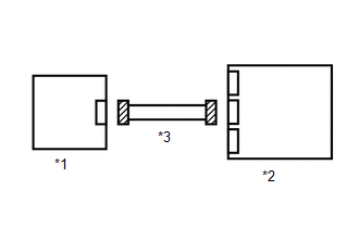
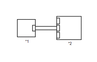
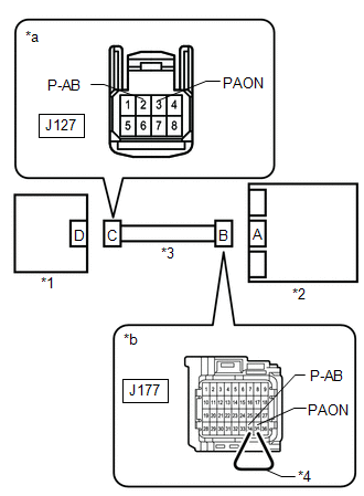
WIRING DIAGRAM 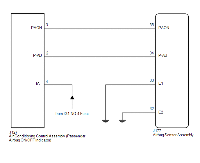
CAUTION / NOTICE / HINT NOTICE:
PROCEDURE
(a) Turn the ignition switch to ON. (b) Check the passenger airbag ON/OFF indicator operation. HINT: Refer to the normal condition of the passenger airbag ON/OFF indicator. Click here
(a) Turn the ignition switch off. (b) Disconnect the cable from the negative (-) battery terminal, and wait for at least 90 seconds. (c) Check that the connectors are properly connected to the airbag sensor assembly and air conditioning control assembly. OK: The connectors are properly connected.
(b) Check that the connectors (on the airbag sensor assembly side and air conditioning control assembly side) are not damaged. OK: The connectors are not deformed or damaged.
(a) Connect the connector to the ari conditioning control assembly. (b) Connect the cable to the negative (-) battery terminal, and wait for at least 2 seconds. (c) Turn the ignition switch to ON. (d) Check the passenger airbag ON/OFF indicator operation. OK: The passenger airbag ON/OFF indicator does not come on.
(b) Connect the cable to the negative (-) battery terminal, and wait for at least 2 seconds. (c) Turn the ignition switch to ON, and wait for at least 60 seconds. (d) Clear the DTCs. Click here (e) Turn the ignition switch off. (f) Turn the ignition switch to ON, and wait for at least 60 seconds. (g) Check for DTCs. Click here
HINT: Codes other than DTC B1660 may be output at this time, but they are not related to this check.
(b) Connect the cable to the negative (-) battery terminal, and wait for at least 2 seconds. (c) Turn the ignition switch to ON. (d) Measure the voltage according to the value(s) in the table below. Standard Voltage:
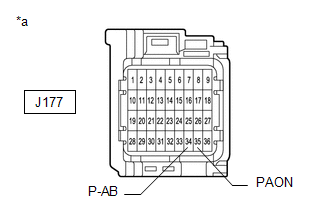
(e) Turn the ignition switch off. (f) Disconnect the cable from the negative (-) battery terminal, and wait for at least 90 seconds. (g) Using a service wire, connect terminals 35 (PAON) and 34 (P-AB) of connector B. NOTICE: Do not forcibly insert the service wire into the terminals of the connector when connecting a service wire. (h) Measure the resistance according to the value(s) in the table below. Standard Resistance:
(i) Disconnect the service wire from connector B. (j) Measure the resistance according to the value(s) in the table below. Standard Resistance:
(a) Turn the ignition switch off. (b) Disconnect the cable from the negative (-) battery terminal, and wait for at least 90 seconds. (c) Check that the connectors are properly connected to the airbag sensor assembly and air conditioning control assembly. OK: The connectors are properly connected.
(b) Check that the connectors (on the airbag sensor assembly side and air conditioning control assembly side) are not damaged. OK: The connectors are not deformed or damaged.
(b) Turn the ignition switch to ON. (c) Measure the voltage according to the value(s) in the table below. Standard Voltage:
(d) Turn the ignition switch off. (e) Disconnect the cable from the negative (-) battery terminal, and wait for at least 90 seconds. (f) Using a service wire, connect terminals 35 (PAON) and 34 (P-AB) of connector B. NOTICE: Do not forcibly insert the service wire into the terminals of the connector when connecting a service wire. (g) Measure the resistance according to the value(s) in the table below. Standard Resistance:
(h) Disconnect the service wire from connector B. (i) Measure the resistance according to the value(s) in the table below. Standard Resistance:
(b) Turn the ignition switch to ON. (c) Measure the voltage according to the value(s) in the table below. Standard Voltage:
(b) Disconnect the cable from the negative (-) battery terminal, and wait for at least 90 seconds. (c) Connect the connector to the air conditioning control assembly. (d) Using a service wire, connect terminal 35 (PAON) and body ground. (e) Using a service wire, connect terminal 34 (P-AB) and body ground. (f) Connect the cable to the negative (-) battery terminal, and wait for at least 2 seconds. (g) Turn the ignition switch to ON. (h) Check the indicator according to the table below. OK:
(i) Disconnect the service wire from airbag sensor assembly.
(b) Disconnect the cable from the negative (-) battery terminal, and wait for at least 90 seconds. (c) Connect the connectors to the airbag sensor assembly. (d) Connect the cable to the negative (-) battery terminal and wait for at least 2 seconds. (e) Turn the ignition switch to ON, and wait for at least 60 seconds. (f) Clear the DTCs. Click here (g) Turn the ignition switch off. (h) Turn the ignition switch to ON, and wait for at least 60 seconds. (i) Check for DTCs. Click here
HINT: Codes other than DTC B1660 may be output at this time, but they are not related to this check.
|
Toyota Tundra Service Manual > Power Tilt And Power Telescopic Steering Column System: IG Power Source Circuit
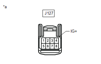
DESCRIPTION When the ignition switch is turned to on, the IG power source circuit supplies positive (+) voltage to the multiplex tilt and telescopic ECU. The multiplex tilt and telescopic ECU also receives ignition switch signals via this circuit. WIRING DIAGRAM CAUTION / NOTICE / HINT HINT: Inspect ...