DESCRIPTION The SRS warning light is located in the combination meter assembly. When the SRS is normal, the SRS warning light comes on for approximately 6 seconds after the engine switch is turned from off on (IG), and then goes off automatically. If there is a malfunction in the SRS, the SRS warning light comes on to inform the driver of a problem. When terminals TC and CG of the DLC3 are connected, DTCs are output by the blinking of the SRS warning light. The SRS is equipped with a voltage-increase circuit (DC-DC converter) in the airbag sensor assembly in case the source voltage drops. When the battery voltage drops, the voltage-increase circuit (DC-DC converter) functions to increase the voltage of the SRS to normal voltage. A malfunction in this circuit is not recorded in the airbag sensor assembly. The SRS warning light automatically goes off when the source voltage returns to normal. The signal to illuminate the SRS warning light is transmitted from the airbag sensor assembly to the combination meter assembly through the CAN communication system. WIRING DIAGRAM 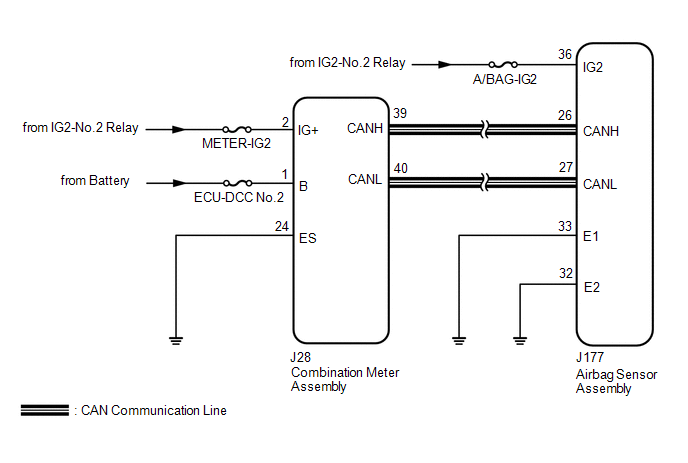
CAUTION / NOTICE / HINT NOTICE:
PROCEDURE
(a) Turn the engine switch on (IG) and check the SRS warning light condition. HINT: The primary check is performed for approximately 6 seconds after the engine switch is turned on (IG).
(a) Measure the battery voltage. Standard voltage: 11 to 14 V HINT: It may be possible to tell whether the battery is discharged by operating the horn. If the voltage is below 11 V, recharge or replace the battery before proceeding to the next step.
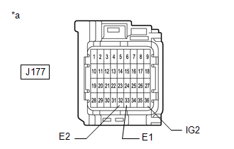
(a) Turn the engine switch off. (b) Disconnect the cable from the negative (-) battery terminal, and wait for at least 90 seconds. (c) Check that the connector is properly connected to the airbag sensor assembly. OK: The connector is properly connected. HINT: If the connector is not properly connected, reconnect the connector and proceed to the next inspection. (d) Disconnect the connector from the airbag sensor assembly. (e) Check that the terminals of the connector are not deformed or damaged. OK: The terminals are not deformed or damaged.
(b) Turn the engine switch on (IG). (c) Operate all components of the electrical systems (defogger, wipers, headlights, heater blower, etc.). (d) Measure the voltage according to the value(s) in the table below. Standard Voltage:
(e) Turn the engine switch off. (f) Measure the resistance according to the value(s) in the table below. Standard Resistance:
(a) Turn the engine switch on (IG) and check the SRS warning light condition. OK: After the primary check period, the SRS warning light turns off for approximately 10 seconds and then turns back on. HINT: The primary check period is approximately 6 seconds after the engine switch is turned on (IG).
(a) Check if a CAN communication DTC is output. Click here
(a) Measure the battery voltage with the engine switch off. Standard voltage: 11 to 14 V HINT: It may be possible to tell whether the battery is discharged by operating the horn. If the voltage is below 11 V, recharge or replace the battery before proceeding to the next step.
(a) Turn the engine switch off. (b) Disconnect the cable from the negative (-) battery terminal, and wait for at least 90 seconds. (c) Check that the connector is properly connected to the airbag sensor assembly. OK: The connector is properly connected. HINT: If the connector is not properly connected, reconnect the connector and proceed to the next inspection. (d) Disconnect the connector from the airbag sensor assembly. (e) Check that the terminals of the connector are not deformed or damaged. OK: The terminals are not deformed or damaged.
(b) Turn the engine switch on (IG). (c) Operate all components of the electrical systems (defogger, wipers, headlights, heater blower, etc.). (d) Measure the voltage according to the value(s) in the table below. Standard Voltage:
(e) Turn the engine switch off. (f) Measure the resistance according to the value(s) in the table below. Standard Resistance:
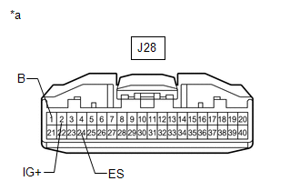
(a) Disconnect the cable from the negative (-) battery terminal, and wait for at least 90 seconds. (b) Check that the connector is properly connected to the combination meter assembly. OK: The connector is properly connected. HINT: If the connector is not properly connected, reconnect the connector and proceed to the next inspection. (c) Disconnect the connector from the combination meter assembly. (d) Check that the terminals of the connector are not deformed or damaged. OK: The terminals are not deformed or damaged.
(b) Turn the engine switch on (IG). (c) Measure the voltage according to the value(s) in the table below. Standard Voltage:
(d) Measure the resistance according to the value(s) in the table below. Standard Resistance:
(a) Disconnect the cable from the negative (-) battery terminal, and wait for at least 90 seconds. (b) Connect the connector to the combination meter assembly. (c) Connect the cable to the negative (-) battery terminal. (d) Turn the engine switch on (IG) and check the SRS warning light condition. OK: After the primary check period, the SRS warning light turns off for approximately 10 seconds and then turns back on. HINT: The primary check period is approximately 6 seconds after the engine switch is turned on (IG).
|
Toyota Tundra Service Manual > Headlight Assembly(for Led Headlight): Removal
REMOVAL CAUTION / NOTICE / HINT HINT: Use the same procedure for the RH and LH sides. The procedure listed below is for the LH side. PROCEDURE 1. REMOVE RADIATOR GRILLE SUB-ASSEMBLY 2. REMOVE FRONT END PANEL LH 3. REMOVE HEADLIGHT ASSEMBLY LH (a) Apply protective tape around the headlight assembly L ...