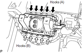
INSTALLATION PROCEDURE 1. INSTALL FRONT PASSENGER AIRBAG ASSEMBLY
(b) Attach the 5 hooks (B) and install the front passenger airbag on the instrument panel.
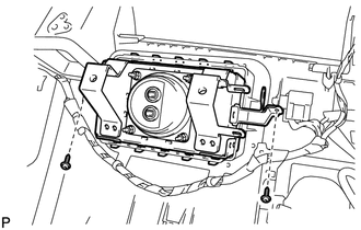
2. INSTALL NO. 3 INSTRUMENT PANEL WIRE (a) Attach the wire harness clamp to install the No. 3 instrument panel wire. (b) Connect the connector. NOTICE: When handling the airbag connector, take care not to damage the airbag wire harness. 3. INSTALL NO. 2 INSTRUMENT PANEL WIRE (a) Attach the wire harness clamp to install the No. 2 instrument panel wire. (b) Connect the 2 connectors. NOTICE: When handling the airbag connector, take care not to damage the airbag wire harness. 4. INSTALL NO. 2 SIDE DEFROSTER NOZZLE DUCT
5. INSTALL NO. 2 HEATER TO REGISTER DUCT
6. INSTALL DEFROSTER NOZZLE ASSEMBLY
7. INSTALL INSTRUMENT PANEL SUB-ASSEMBLY HINT:
8. CONNECT CABLE TO NEGATIVE BATTERY TERMINAL NOTICE: When disconnecting the cable, some systems need to be initialized after the cable
is reconnected (See page 9. CHECK SRS WARNING LIGHT (a) Check the SRS warning light (see page |
Toyota Tundra Service Manual > Power Window Control System(w/ Jam Protection Function): Parts Location
PARTS LOCATION ILLUSTRATION *A for Double Cab - - *1 FRONT DOOR COURTESY LIGHT SWITCH RH *2 FRONT DOOR COURTESY LIGHT SWITCH LH *3 POWER WINDOW REGULATOR SWITCH ASSEMBLY *4 POWER WINDOW REGULATOR MASTER SWITCH ASSEMBLY *5 REAR POWER WINDOW REGULATOR SWITCH ASSEMBLY RH *6 REAR POWER WINDOW REGULATOR ...