REMOVAL PROCEDURE 1. PRECAUTION NOTICE: After turning the ignition switch off, waiting time may be required before disconnecting
the cable from the battery terminal. Therefore, make sure to read the disconnecting
the cable from the battery terminal notice before proceeding with work (See page
2. DISCONNECT CABLE FROM NEGATIVE BATTERY TERMINAL CAUTION: Wait at least 90 seconds after disconnecting the cable from the negative (-) battery terminal to prevent airbag and seat belt pretensioner activation. NOTICE: When disconnecting the cable, some systems need to be initialized after the cable
is reconnected (See page 3. REMOVE INSTRUMENT PANEL SUB-ASSEMBLY HINT:
4. REMOVE DEFROSTER NOZZLE ASSEMBLY
5. REMOVE NO. 2 HEATER TO REGISTER DUCT
6. REMOVE NO. 2 SIDE DEFROSTER NOZZLE DUCT
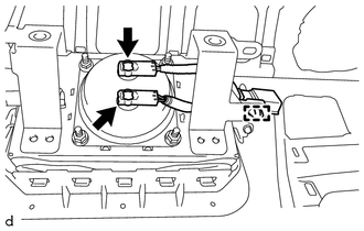
7. REMOVE NO. 2 INSTRUMENT PANEL WIRE
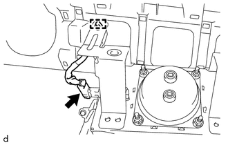
(b) Detach the wire harness clamp and remove the No. 2 instrument panel wire. 8. REMOVE NO. 3 INSTRUMENT PANEL WIRE
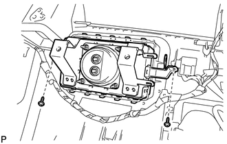
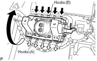
(b) Detach the wire harness clamp and remove the No. 3 instrument panel wire. 9. REMOVE FRONT PASSENGER AIRBAG ASSEMBLY
(c) Detach the 5 hooks (B) and remove the front passenger airbag from the instrument panel. |
Toyota Tundra Service Manual > Dynamic Radar Cruise Control System: Data List / Active Test
DATA LIST / ACTIVE TEST READ DATA LIST NOTICE: In the table below, the values listed under "Normal Condition" are reference values. Do not depend solely on these reference values when deciding whether a part is faulty or not. HINT: Using the Techstream to read the Data List allows the values or stat ...