DESCRIPTION The passenger side buckle switch circuit consists of the occupant classification ECU and the front seat inner belt RH. DTC B1771 is recorded when a malfunction is detected in the passenger side buckle switch circuit. Troubleshoot DTC B1771 first when DTCs B1771 and B1795 are output simultaneously.
HINT:
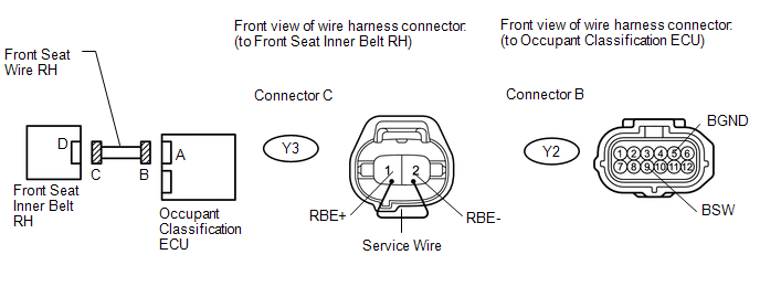
WIRING DIAGRAM 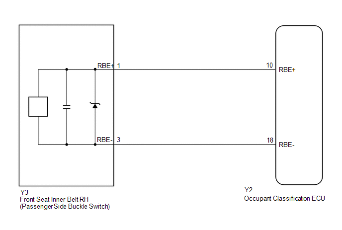
CAUTION / NOTICE / HINT NOTICE:
HINT:
PROCEDURE
(a) Turn the ignition switch to ON, and wait for at least 60 seconds. (b) Clear the DTCs stored in the memory (see page
HINT: First clear DTCs stored in the occupant classification ECU and then in the center airbag sensor. (c) Turn the ignition switch off. (d) Turn the ignition switch to ON, and wait for at least 60 seconds. (e) Check for DTCs (see page OK: DTC B1771 is not output. HINT: Codes other than DTC B1771 may be output at this time, but they are not related to this check.
(a) Turn the ignition switch off. (b) Disconnect the negative (-) terminal cable from the battery, and wait for at least 90 seconds. (c) Check that the connectors are properly connected to the occupant classification ECU and the front seat inner belt RH. OK: Connectors are properly connected.
(a) Disconnect the connectors from the occupant classification ECU and the front seat inner belt RH. (b) Check that the connectors (on the occupant classification ECU side and passenger
side buckle switch side) are not damaged (see page
OK: Connectors are not deformed or damaged.
(a) Connect the negative (-) terminal cable to the battery, and wait for at least 2 seconds. (b) Turn the ignition switch to ON, and wait for at least 60 seconds. (c) Measure the voltage according to the value(s) in the table below. Standard voltage:
(d) Turn the ignition switch off. (e) Disconnect the negative (-) terminal cable from the battery, and wait for at least 90 seconds. (f) Using a service wire, connect terminals 1 (RBE+) and 2 (RBE-) of connector C. NOTICE: Do not forcibly insert the service wire into the terminals of the connector. (g) Measure the resistance according to the value(s) in the table below. Standard resistance:
(h) Disconnect the service wire from connector C. (i) Measure the resistance according to the value(s) in the table below. Standard resistance:
(a) Connect the connectors to the occupant classification ECU and the front seat inner belt RH. (b) Connect the negative (-) terminal cable to the battery, and wait for at least 2 seconds. (c) Turn the ignition switch to ON, and wait for at least 60 seconds. (d) Clear the DTCs stored in the memory (see page
HINT: First clear DTCs stored in the occupant classification ECU and then in the center airbag sensor. (e) Turn the ignition switch off. (f) Turn the ignition switch to ON, and wait for at least 60 seconds. (g) Check for DTCs (see page OK: DTC B1771 is not output. HINT: Codes other than DTC B1771 may be output at this time, but they are not related to this check.
(a) Turn the ignition switch off. (b) Disconnect the negative (-) terminal cable from the battery, and wait for at least 90 seconds. (c) Replace the front seat inner belt RH (see page
HINT: Perform the inspection using parts from a normal vehicle when possible. (d) Connect the negative (-) terminal cable to the battery, and wait for at least 2 seconds. (e) Turn the ignition switch to ON, and wait for at least 60 seconds. (f) Clear the DTCs stored in the memory (see page
HINT: First clear DTCs stored in the occupant classification ECU and then in the center airbag sensor. (g) Turn the ignition switch off. (h) Turn the ignition switch to ON, and wait for at least 60 seconds. (i) Check for DTCs (see page OK: DTC B1771 is not output. HINT: Codes other than DTC B1771 may be output at this time, but they are not related to this check.
(a) Turn the ignition switch off. (b) Disconnect the negative (-) terminal cable from the battery, and wait for at least 90 seconds. (c) Replace the occupant classification ECU.
HINT: Perform the inspection using parts from a normal vehicle when possible. (d) Connect the negative (-) terminal cable to the battery, and wait for at least 2 seconds. (e) Turn the ignition switch to ON, and wait for at least 60 seconds. (f) Clear the DTCs stored in the memory (see page
HINT: If the DTCs are not cleared at this time, past DTCs will remain.
(a) Connect the Techstream to the DLC3. (b) Turn the ignition switch to ON, and wait for at least 60 seconds. (c) Using the Techstream, perform the zero point calibration (see page
(a) Using the Techstream, perform the sensitivity check (see page
Standard range: 27 to 33 kg (59.5 to 72.8 lb)
|
Toyota Tundra Service Manual > Meter / Gauge System: How To Proceed With Troubleshooting
CAUTION / NOTICE / HINT HINT: Use these procedures to troubleshoot the meter / gauge system. *: Use the Techstream. PROCEDURE 1. VEHICLE BROUGHT TO WORKSHOP NEXT 2. INSPECT BATTERY VOLTAGE (a) Measure the battery voltage with the ignition switch off. Standard voltage: 11 to 14 V If the voltage is be ...


