DESCRIPTION The front occupant detection sensor LH circuit consists of the occupant classification ECU and the front occupant detection sensor LH. DTC B1780 is set when a malfunction is detected in the front occupant detection sensor LH circuit.
HINT:
WIRING DIAGRAM 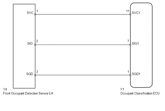
CAUTION / NOTICE / HINT NOTICE:
HINT:
PROCEDURE
(a) Turn the ignition switch to ON, and wait for at least 60 seconds. (b) Clear any DTCs stored in the memory (see page
HINT:
(c) Turn the ignition switch off. (d) Turn the ignition switch to ON, and wait for at least 60 seconds. (e) Using the Techstream, check for DTCs of the occupant classification ECU (see
page OK: DTC B1780 is not output. HINT: DTCs other than DTC B1780 may be output at this time, but they are not related to this check.
(a) Turn the ignition switch off. (b) Disconnect the negative (-) terminal cable from the battery, and wait for at least 90 seconds. (c) Check that the connectors are properly connected to the occupant classification ECU and the front occupant detection sensor LH. OK: Connectors are properly connected.
(a) Check that the connectors (on the occupant classification ECU side and front
occupant detection sensor LH side) are not damaged (see page
OK: Connectors are not deformed or damaged.
(a) Disconnect the connectors from the occupant classification ECU and the front occupant detection sensor LH. (b) Connect the negative (-) terminal cable to the battery, and wait for at least 2 seconds. (c) Turn the ignition switch to ON, and wait for at least 60 seconds. (d) Measure the voltage according to the value(s) in the table below. Standard voltage:
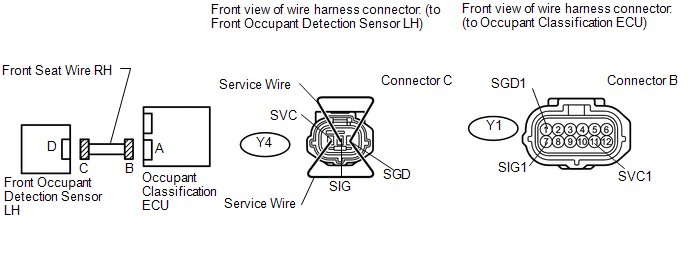
(e) Turn the ignition switch off. (f) Disconnect the negative (-) terminal cable from the battery, and wait for at least 90 seconds. (g) Using service wires, connect terminals 1 (SVC) and 3 (SGD), and connect terminals 2 (SIG) and 3 (SGD) of connector C. NOTICE: Do not forcibly insert the service wires into the terminals of the connector. (h) Measure the resistance according to the value(s) in the table below. Standard resistance:
(i) Disconnect the service wires from connector C. (j) Measure the resistance according to the value(s) in the table below. Standard resistance:
(a) Connect the connectors to the occupant classification ECU and the front occupant detection sensor LH. (b) Connect the negative (-) terminal cable to the battery, and wait for at least 2 seconds. (c) Turn the ignition switch to ON, and wait for at least 60 seconds. (d) Clear any DTCs stored in the memory (see page
HINT:
(e) Turn the ignition switch off. (f) Turn the ignition switch to ON, and wait for at least 60 seconds. (g) Using the Techstream, check for DTCs of the occupant classification ECU (see
page OK: DTC B1780 is not output. HINT: DTCs other than DTC B1780 may be output at this time, but they are not related to this check.
(a) Turn the ignition switch off. (b) Disconnect the negative (-) terminal cable from the battery, and wait for at least 90 seconds. (c) Replace the occupant classification ECU.
HINT: Perform the inspection using parts from a normal vehicle when possible.
(a) Connect the negative (-) terminal cable to the battery, and wait for at least 2 seconds. (b) Connect the Techstream to the DLC3. (c) Turn the ignition switch to ON, and wait for at least 60 seconds. (d) Using the Techstream, perform the zero point calibration (see page
(a) Using the Techstream, perform the sensitivity check (see page
Standard range: 27 to 33 kg (59.5 to 72.8 lb)
(a) Turn the ignition switch to ON, and wait for at least 60 seconds. (b) Clear any DTCs stored in the memory (see page
HINT:
(c) Turn the ignition switch off. (d) Turn the ignition switch to ON, and wait for at least 60 seconds. (e) Using the Techstream, check for DTCs of the occupant classification ECU (see
page OK: DTC B1780 is not output. HINT: DTCs other than DTC B1780 may be output at this time, but they are not related to this check.
(a) Turn the ignition switch off. (b) Disconnect the negative (-) terminal cable from the battery, and wait for at least 90 seconds. (c) Replace the front seat frame with adjuster RH (see page
HINT: Perform the inspection using parts from a normal vehicle when possible.
(a) Connect the Techstream to the DLC3. (b) Connect the negative (-) terminal cable to the battery, and wait for at least 2 seconds. (c) Turn the ignition switch to ON, and wait for at least 60 seconds. (d) Using the Techstream, perform the zero point calibration (see page
(a) Using the Techstream, perform the sensitivity check (see page
Standard range: 27 to 33 kg (59.5 to 72.8 lb)
|
Toyota Tundra Service Manual > Dynamic Radar Cruise Control System: Front Radar Sensor (C1A10)
DESCRIPTION C1A10 is output when there is an internal malfunction in the millimeter wave radar sensor assembly. DTC No. Detection Item DTC Detection Condition Trouble Area C1A10 Front Radar Sensor While the vehicle speed is 36 km/h (22 mph) or more and the dynamic radar cruise control system is oper ...


