|
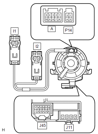
(b) Check the spiral cable sub-assembly.
(1) Set the spiral cable sub-assembly to the center position (see page
 ). ).
(2) After setting the spiral cable sub-assembly to the center position,
rotate the spiral cable sub-assembly 2.5 times clockwise, and measure the
resistance as shown. Then rotate the spiral cable sub-assembly 5 times counterclockwise,
measure the resistance according to the U4 (uecs) in the table below.
Standard resistance:
|
Tester Connection
|
Condition
|
Specified Condition
|
|
J11-1 - I1-2
|
Always
|
Below 1 Ω
|
|
J11-2 - I1-1
|
|
J11-3 - I2-1
|
|
J11-4 - I2-2
|
|
J45-6 - A-10
|
|
J45-5 - A-9
|
|
J45-4 - A-8
|
|
J45-3 - A-7
|
|
J45-2 - A-6
|
|
J45-2 - P14-4
|
|
J45-1 - P14-3
|
|
J45-12 - A-5
|
|
J45-11 - A-4
|
|
J45-10 - A-3
|
|
J45-9 - A-2
|
|
J45-8 - A-1
|
|
J45-8 - P14-2
|
|
J45-7 - P14-1
|
(3) After setting the spiral cable sub-assembly to the center position,
rotate the spiral cable sub-assembly 2.5 times clockwise. Then while rotating
the spiral cable 5 times counterclockwise, measure the resistance according
to the U4 (uecs) in the table below.
Standard resistance:
|
Tester Connection
|
Condition
|
Specified Condition
|
|
J11-1 - I1-2
|
Always
|
Below 1 Ω
|
|
J11-2 - I1-1
|
|
J11-3 - I2-1
|
|
J11-4 - I2-2
|
|
J45-6 - A-10
|
|
J45-5 - A-9
|
|
J45-4 - A-8
|
|
J45-3 - A-7
|
|
J45-2 - A-6
|
|
J45-2 - P14-4
|
|
J45-1 - P14-3
|
|
J45-12 - A-5
|
|
J45-11 - A-4
|
|
J45-10 - A-3
|
|
J45-9 - A-2
|
|
J45-8 - A-1
|
|
J45-8 - P14-2
|
|
J45-7 - P14-1
|
NOTICE:
As the spiral cable sub-assembly may break, do not rotate the spiral
cable sub-assembly more than the specified amount.
|