DESCRIPTION The solar sensor, which is installed on the upper side of the instrument panel, detects sunlight and controls the air conditioning in AUTO mode. The output current from the solar sensor varies according to the amount of sunlight. When the sunlight increases, the output current increases. As the sunlight decreases, the output current decreases. The air conditioning amplifier detects output current from the solar sensor. 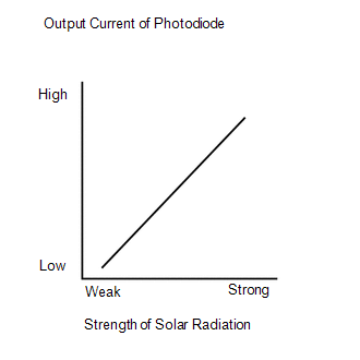
WIRING DIAGRAM 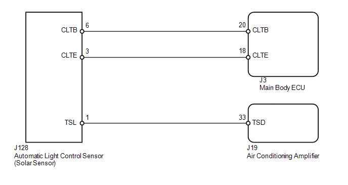
CAUTION / NOTICE / HINT HINT: If DTC B1244 is output at the same time, troubleshoot DTC B1244 first (see page
PROCEDURE
(a) Use the Data List to check if the driver side solar sensor is functioning properly. Air Conditioner
OK: The display is as specified in the normal condition. Result
(a) Disconnect the J128 solar sensor connector. (b) Measure the resistance according to the value(s) in the table below. Standard resistance:
(c) Measure the voltage according to the value(s) in the table below. Standard voltage:
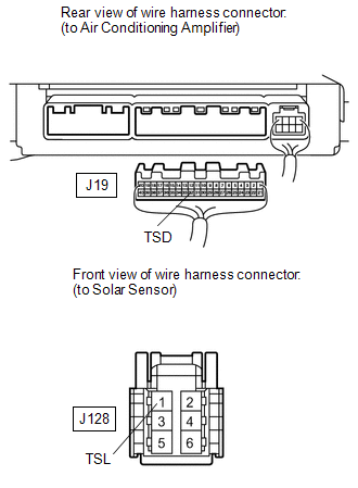
(a) Disconnect the J19 air conditioning amplifier connector. (b) Disconnect the J128 solar sensor connector. (c) Measure the resistance according to the value(s) in the table below. Standard resistance:
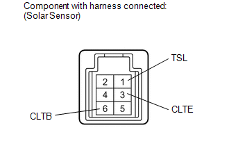
(a) Remove the solar sensor with its connector still connected (see page
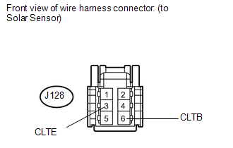
(b) Apply battery voltage between terminals 6 (CLTB) and 3 (CLTE) of the solar sensor. (c) Measure the voltage according to the value(s) in the table below. Standard voltage:
HINT:
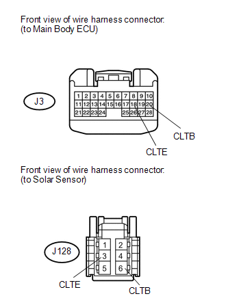
(a) Disconnect the J3 ECU connector. (b) Disconnect the J128 solar sensor connector. (c) Measure the resistance according to the value(s) in the table below. Standard resistance:
|
Toyota Tundra Service Manual > Front Brake: Removal
REMOVAL CAUTION / NOTICE / HINT HINT: Use the same procedures for the LH side and RH side. The procedures listed below are for the LH side. PROCEDURE 1. REMOVE FRONT WHEEL 2. REMOVE FRONT DISC BRAKE PAD KIT (a) Remove the pin hold clip. NOTICE: The pin hold clip can be used again if it has sufficien ...


