REMOVAL PROCEDURE 1. PRECAUTION NOTICE: After
turning the ignition switch off, waiting time may be required before
disconnecting the cable from the battery terminal. Therefore, make sure
to read the disconnecting the cable from the battery terminal notice
before proceeding with work (See page 2. DISCONNECT CABLE FROM NEGATIVE BATTERY TERMINAL NOTICE: When disconnecting the cable, some systems need to be initialized after the cable is reconnected (See page
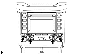
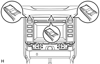
3. REMOVE SHIFT LEVER KNOB SUB-ASSEMBLY 4. REMOVE REAR UPPER CONSOLE PANEL SUB-ASSEMBLY 5. REMOVE UPPER CONSOLE PANEL SUB-ASSEMBLY 6. REMOVE AIR CONDITIONING CONTROL ASSEMBLY 7. REMOVE RADIO AND DISPLAY RECEIVER ASSEMBLY
(c) Disconnect each connector and remove the radio and display receiver assembly with bracket. 8. REMOVE NO. 1 NAVIGATION WIRE (w/ Satellite Radio)
9. REMOVE NO. 1 RADIO RECEIVER BRACKET 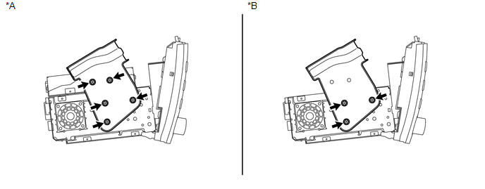 Text in Illustration Text in Illustration
(a) w/ Satellite Radio: Remove the 5 bolts and No. 1 radio receiver bracket. (b) w/o Satellite Radio: Remove the 3 bolts and No. 1 radio receiver bracket. 10. REMOVE NO. 2 RADIO RECEIVER BRACKET 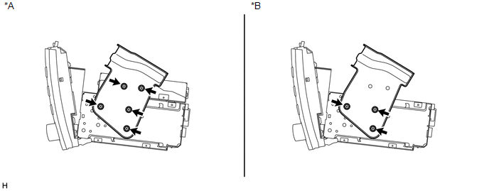 Text in Illustration Text in Illustration
(a) w/ Satellite Radio: Remove the 5 bolts and No. 2 radio receiver bracket. (b) w/o Satellite Radio: Remove the 3 bolts and No. 2 radio receiver bracket. 11. REMOVE STEREO COMPONENT TUNER ASSEMBLY (w/ Satellite Radio)
|
Toyota Tundra Service Manual > Vehicle Stability Control System: Control Module Communication Bus OFF (U0073,U0100,U0114,U0123,U0126)
DESCRIPTION The skid control ECU (brake actuator assembly) receives signals from the ECM, steering angle sensor (spiral with sensor cable sub-assembly), yaw rate and acceleration sensor (airbag sensor assembly) and 4WD control ECU via CAN communication. DTC No. Detection Item DTC Detection Condition ...