SYSTEM DIAGRAM 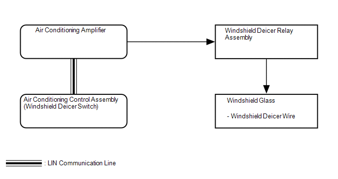 Communication Table Communication Table
|
Toyota Tundra Service Manual > Air Pump: Removal
REMOVAL PROCEDURE 1. DISCONNECT FRONT FENDER LINER RH (See page ) HINT: It is not necessary to fully remove the front fender liner RH. Partially remove it so that the air pump assembly with bracket can be removed in a later step. 2. DISCONNECT FRONT FENDER APRON SEAL RH (a) Using a clip remover, rem ...


