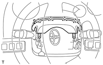
Components COMPONENTS ILLUSTRATION 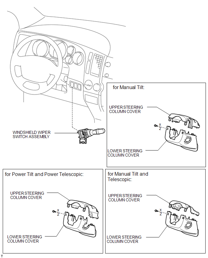
Inspection INSPECTION PROCEDURE 1. INSPECT WIPER AND WASHER SWITCH ASSEMBLY 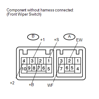
(a) Measure the resistance according to the value(s) in the table below. Standard resistance: Windshield wiper switch
If the result is not as specified, replace the switch assembly. (b) Check the intermittent operation. 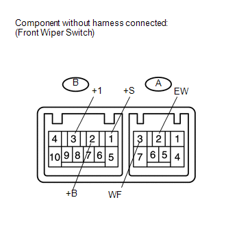
(1) Connect the voltmeter's positive (+) lead to terminal B-3 (+1) and the negative (-) lead to terminal A-2 (EW). (2) Connect the battery's positive (+) lead to terminal B-2 (+B) and the negative (-) lead to terminals A-2 (EW) and B-1 (+S). (3) Turn the wiper switch to the INT position. (4) Connect the battery's positive (+) lead to terminal B-1 (+S) for 5 seconds. (5) Connect the battery's negative (-) lead to terminal B-1 (+S). Operate the intermittent wiper relay and check the voltage between terminals B-3 (+1) and A-2 (EW). OK: Refer to illustration below. 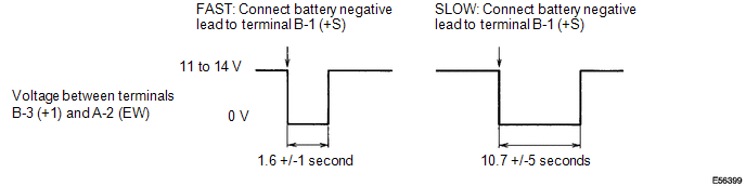
If the result is not as specified, replace the switch assembly. (c) Check the washer operation. 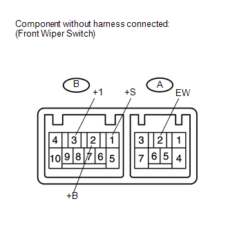
(1) Turn the wiper switch OFF. (2) Connect the battery's positive (+) lead to terminal B-2 (+B) and the negative (-) lead to terminals B-1 (+S) and A-2 (EW). (3) Connect the voltmeter's positive (+) lead to terminal B-3 (+1) and the negative (-) lead to terminal A-2 (EW). (4) Turn the washer switch ON and OFF, and check the voltage between terminals B-3 (+1) and A-2 (EW). OK: Refer to illustration below. 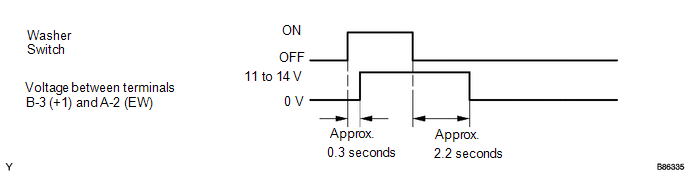
If the result is not as specified, replace the switch assembly. Installation INSTALLATION PROCEDURE 1. INSTALL WINDSHIELD WIPER SWITCH ASSEMBLY
(b) Connect the 2 connectors. 2. INSTALL UPPER STEERING COLUMN COVER
(b) Attach the claw to install the upper steering column cover. 3. INSTALL LOWER STEERING COLUMN COVER
(b) Using a screwdriver, while turning the steering wheel to the right and left, install the 2 screws and lower steering column cover. Removal REMOVAL PROCEDURE 1. REMOVE LOWER STEERING COLUMN COVER (a) for Manual Tilt and Telescopic: (1) Operate the tilt and telescopic lever to fully extend and lower the steering column. (b) for Power Tilt and Telescopic: (1) Turn the ignition switch ON. Operate the tilt and telescopic switch to fully extend and lower the steering column.
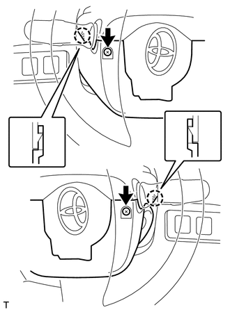
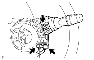
(d) Detach the 2 claws to remove the lower steering column cover. NOTICE: Do not damage the tilt and telescopic switch. 2. REMOVE UPPER STEERING COLUMN COVER
(b) Detach the claw to remove the upper steering column cover. 3. REMOVE WINDSHIELD WIPER SWITCH ASSEMBLY
(b) Detach the claw and remove the wiper switch. NOTICE: Do not push the claw with excessive force as it may brake. |