Toyota Tundra Service Manual: Inspection

INSPECTION

PROCEDURE

1. INSPECT STEERING PAD SWITCH ASSEMBLY

(a) Measure the resistance according to the value(s) in the table below.

*A

w/ Lane Departure Alert System

-

-

*1

VOLUME+

*2

VOLUME-

*3

SEEK+

*4

SEEK-

*5

VOICE

*6

MODE HOLD

*7

OFF HOOK

*8

ON HOOK

*9

UP

*10

DOWN

*11

RIGHT

*12

LEFT

*13

ENTER

*14

BACK

*15

TOP

*16

ACC

*17

LDA

-

-

*a

Component without harness connected

-

-

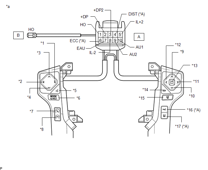
Standard Resistance:

Tester Connection

Switch Condition

Specified Condition

*:w/ Lane Departure Alert System

A2 (+DP) - A7 (EAU)

No switch is pushed

100 kΩ or higher

ENTER switch is pushed

Below 2.5 Ω

TOP switch is pushed

312 to 345 Ω

BACK switch is pushed

950 to 1050 Ω

A3 (+DP2) - A7 (EAU)

No switch is pushed

100 kΩ or higher

RIGHT switch is pushed

2954 to 3265 Ω

LEFT switch is pushed

Below 2.5 Ω

UP switch is pushed

312 to 345 Ω

DOWN switch is pushed

950 to 1050 Ω

A9 (AU2) - A7 (EAU)

No switch is pushed

100 kΩ or higher

MODE switch is pushed

Below 2.5 Ω

ON HOOK switch is pushed

312 to 345 Ω

OFF HOOK switch is pushed

950 to 1050 Ω

VOICE switch is pushed

2954 to 3265 Ω

A10 (AU1) - A7 (EAU)

No switch is pushed

100 kΩ or higher

SEEK+ switch is pushed

Below 2.5 Ω

SEEK- switch is pushed

312 to 345 Ω

VOLUME+ switch is pushed

950 to 1050 Ω

VOLUME- switch is pushed

2954 to 3265 Ω

A4 (DIST) - A6 (ECC)*

No switch is pushed

100 kΩ or higher

ACC switch is pushed

Below 2.5 Ω

LDA switch is pushed

228 to 252 Ω

B (HO) - A1 (HO)

Always

Below 2.5 Ω

If the result is not as specified, replace the steering pad switch assembly.

(b) Check the illumination.

(1) Connect the battery positive (+) lead to terminal A5 (IL+2) and the negative (-) lead to terminal A8 (IL-2) of the steering pad switch assembly connector.

(2) Check that the switch illumination comes on.

OK:

Steering pad switch illumination comes on.

If the result is not as specified, replace the steering pad switch assembly.

    Components

    Installation

    See More:

    Toyota Tundra Service Manual > Ultrasonic Sensor(for Front Side): Installation
    INSTALLATION PROCEDURE 1. INSTALL NO. 1 ULTRASONIC SENSOR (for Steel Type Bumper) (a) Install the No. 1 ultrasonic sensor as shown in the illustration. NOTICE: Do not damage the bumper with the protrusion when installing the No. 1 ultrasonic sensor. 2. INSTALL NO. 1 ULTRASONIC SENSOR RETAINER (for S ...

    Toyota Tundra Owners Manual

    Toyota Tundra Service Manual

    © 2024 Copyright www.ttundra.com
    0.0135