DESCRIPTION Each unit of the navigation system connected to the AVC-LAN (communication bus) transfers the switch signals using the AVC-LAN. If a short to +B or short to ground occurs in the AVC-LAN, the navigation system will not function normally because communication is not possible. WIRING DIAGRAM 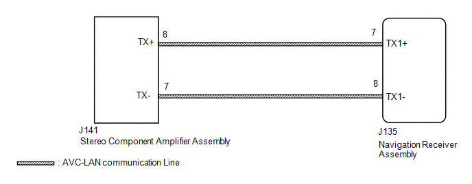 CAUTION / NOTICE / HINT HINT: The navigation receiver assembly is the master unit. PROCEDURE
 (a) for Column Shift Type: (1) Remove the navigation receiver assembly with the connector(s) still connected (See page
(b) for Floor Shift Type: (1) Remove the navigation receiver assembly with the connector(s) still connected (See page
(c) Measure the resistance according to the value(s) in the table below. Standard Resistance:
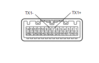
(a) Disconnect the J135 navigation receiver assembly connector. (b) Disconnect the J141 stereo component amplifier assembly connector. (c) Measure the resistance according to the value(s) in the table below. Standard Resistance:
(a) Disconnect and reconnect each slave unit one by one until the master unit returns to normal operation. HINT:
OK: Master unit returns to normal operation. Result
|
Toyota Tundra Service Manual > Hazard Warning Switch: Inspection
INSPECTION PROCEDURE 1. INSPECT AIR CONDITIONING CONTROL ASSEMBLY (HAZARD WARNING SWITCH) (a) Measure the resistance according to the value(s) in the table below. Standard Resistance: Tester Connection Switch Condition Specified Condition 1 (HAZ) - 5 (GND) Hazard warning switch off 10 kΩ or higher ...

 ).
).


