PARTS LOCATION ILLUSTRATION 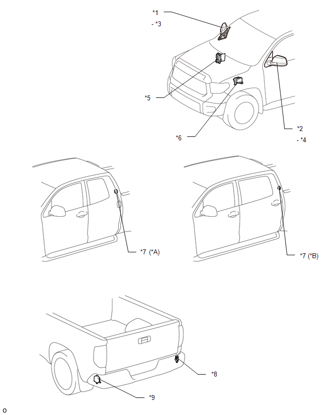
ILLUSTRATION 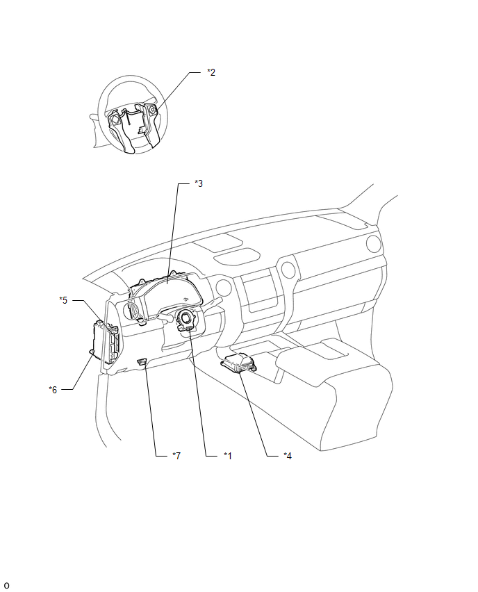
|
Toyota Tundra Service Manual > Refrigerant(for Hfo-1234yf(r1234yf)): Replacement
REPLACEMENT PROCEDURE 1. RECOVER REFRIGERANT FROM REFRIGERATION SYSTEM (a) Start the engine. (b) Operate the cooler compressor under the conditions shown below: Item Condition Operating Time 3 minutes or more Temperature setting Max cool Blower speed High Engine Idling A/C switch On This causes most ...


