DESCRIPTION This circuit provides power to operate the blind spot monitor sensor. WIRING DIAGRAM 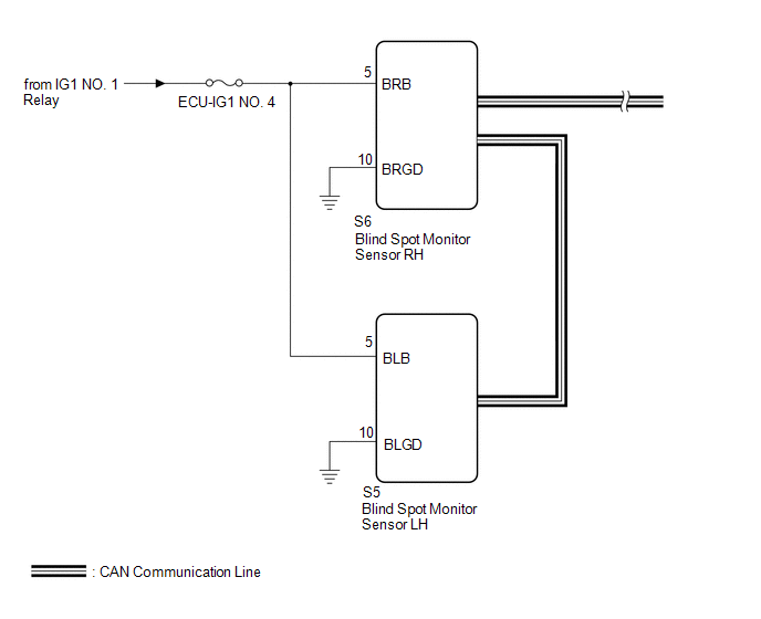 CAUTION / NOTICE / HINT NOTICE: Inspect the fuses for circuits related to this system before performing the following procedure. PROCEDURE
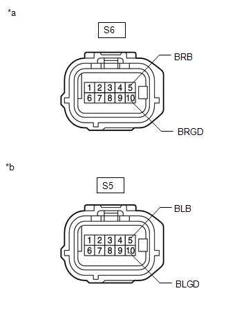
(b) Disconnect the blind spot monitor sensor LH connector. (c) Measure the resistance according to the value(s) in the table below. Standard Resistance:
(d) Measure the voltage according to the value(s) in the table below. Standard Voltage:
|
Toyota Tundra Service Manual > Multiplex Tilt And Telescopic Ecu(for Power Tilt And Power Telescopic Steering Column): Installation
INSTALLATION PROCEDURE 1. INSTALL MULTIPLEX TILT AND TELESCOPIC ECU (a) Attach the claw to install the multiplex tilt and telescopic ECU. (b) Connect the ECU connector. 2. INSTALL NO. 3 AIR DUCT SUB-ASSEMBLY Click here 3. INSTALL LOWER NO. 1 INSTRUMENT PANEL AIRBAG ASSEMBLY Click here 4. INSTALL LOW ...