DESCRIPTION The clearance warning buzzer is installed in the combination meter assembly. WIRING DIAGRAM 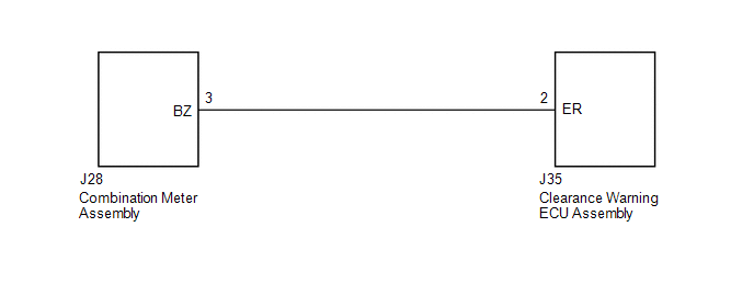 PROCEDURE
(a) Disconnect the J35 clearance warning ECU assembly connector. (b) Disconnect the J28 combination meter assembly connector. (c) Measure the resistance according to the value(s) in the table below. Standard Resistance:
(a) Replace the combination meter assembly with a normally functioning or new one (See page
(b) Check that the clearance warning buzzer operates normally. OK: Clearance warning buzzer operates normally.
|
Toyota Tundra Service Manual > Forward Recognition Camera System: How To Proceed With Troubleshooting
CAUTION / NOTICE / HINT HINT: Use these procedures to troubleshoot the forward recognition camera system. *: Use the Techstream. PROCEDURE 1. VEHICLE BROUGHT TO WORKSHOP NEXT 2. INSPECT BATTERY (a) Measure the battery voltage with the ignition switch off. Standard voltage: 11 to 14 V If the voltage ...


