DESCRIPTION The No. 1 ultrasonic sensor sends and receives ultrasonic waves. Based on the received wave, the sensor calculates the approximate distance value between the vehicle and the obstacle, and sends the distance value as a signal to the clearance warning ECU assembly. WIRING DIAGRAM 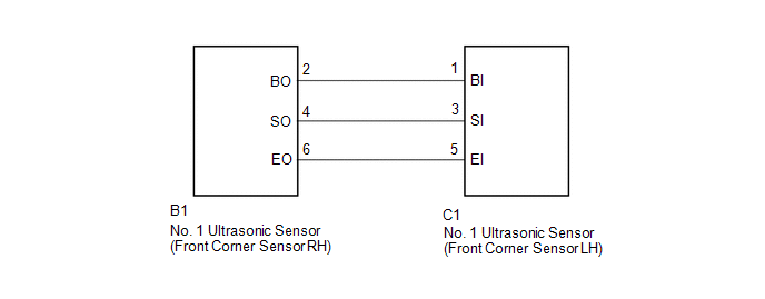 PROCEDURE
(a) Remove the No. 1 ultrasonic sensor (front corner sensor LH) (See page
(b) Inspect the No. 1 ultrasonic sensor (front corner sensor LH) (See page
(a) Disconnect the C1 No. 1 ultrasonic sensor (front corner sensor LH) connector. (b) Disconnect the B1 No. 1 ultrasonic sensor (front corner sensor RH) connector. (c) Measure the resistance according to the value(s) in the table below. Standard Resistance:
|
Toyota Tundra Service Manual > Wireless Door Lock Control System: Operation Check
OPERATION CHECK NOTICE WHEN CHECKING THE FOLLOWING (a) Operation conditions (with customize item "Wireless Lock Function with Doors Open" or "Wireless Lock When Door Opened" "ON"): (1) This wireless door lock control function operates only when the following 2 condition ...


