DESCRIPTION The No. 1 ultrasonic sensor sends and receives ultrasonic waves. Based on the received wave, the sensor calculates the approximate distance value between the vehicle and the obstacle, and sends the distance value as a signal to the clearance warning ECU assembly. WIRING DIAGRAM 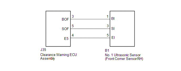 PROCEDURE
(a) Remove the No. 1 ultrasonic sensor (front corner sensor RH) (See page
(b) Inspect the No. 1 ultrasonic sensor (front corner sensor RH) (See page
(a) Disconnect the B1 No. 1 ultrasonic sensor (front corner sensor RH) connector. (b) Disconnect the J35 clearance warning ECU assembly connector. (c) Measure the resistance according to the value(s) in the table below. Standard Resistance:
|
Toyota Tundra Service Manual > High Beam Main Switch: Inspection
INSPECTION PROCEDURE 1. INSPECT AUTO HIGH BEAM SWITCH (a) Check the resistance. (1) Measure the resistance according to the value(s) in the table below. Standard Resistance: Tester Connection Switch Condition Specified Condition If the result is not as specified, replace the auto high beam switch. 6 ...


