DESCRIPTION This circuit is the power source circuit to operate the clearance warning ECU assembly. WIRING DIAGRAM 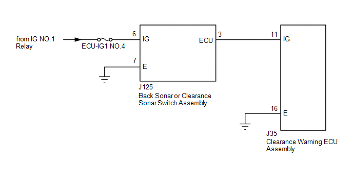 CAUTION / NOTICE / HINT NOTICE: Inspect the fuses for circuits related to this system before performing the following procedure. PROCEDURE
(b) Measure the voltage according to the value(s) in the table below. Standard Voltage:
(c) Measure the resistance according to the value(s) in the table below. Standard Resistance:
(a) Remove the back sonar or clearance sonar switch assembly (See page
(b) Inspect the back sonar or clearance sonar switch assembly (See page
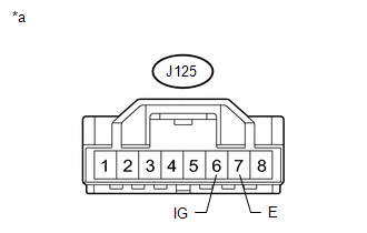
(a) Disconnect the J35 clearance warning ECU assembly connector. (b) Disconnect the J125 back sonar or clearance sonar switch assembly connector. (c) Measure the resistance according to the value(s) in the table below. Standard Resistance:
|
Toyota Tundra Service Manual > Seat Belt Warning System: Customize Parameters
CUSTOMIZE PARAMETERS PROCEDURE 1. CUSTOMIZE SEAT BELT WARNING SYSTEM HINT: The following items can be customized. NOTICE: When the customer requests a change in a function, first make sure that the function can be customized. Be sure to make a note of the current settings before customizing. When tr ...


 ).
).
