TERMINALS OF ECU 1. CHECK NAVIGATION RECEIVER ASSEMBLY 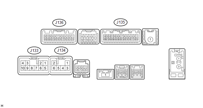 (a) Disconnect the J133 and J135 navigation receiver assembly connectors. (b) Measure the voltage and resistance according to the value(s) in the table below.
(c) Reconnect the J133 and J135 navigation receiver assembly connectors. (d) Measure the voltage and waveform according to the value(s) in the table below.
(e) Using an oscilloscope, check the waveform. 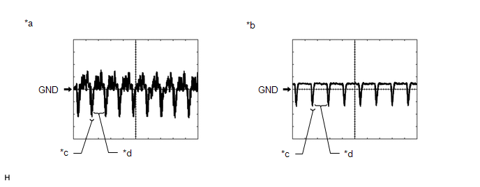
(1) Waveform 1 Measurement Condition
HINT: The video waveform changes according to the image sent by the television camera assembly. (2) Waveform 2 Measurement Condition
HINT: The video waveform changes according to the image sent by the television camera assembly. |
Toyota Tundra Service Manual > Airbag System: Short in D Squib Circuit (B1800-B1803)
DESCRIPTION The driver side squib circuit consists of the airbag sensor assembly, spiral with sensor cable sub-assembly and horn button assembly. The circuit instructs the SRS to deploy when deployment conditions are met. These DTCs are stored when a malfunction is detected in the driver side squib ...


