Toyota Tundra Service Manual: Components

COMPONENTS

ILLUSTRATION
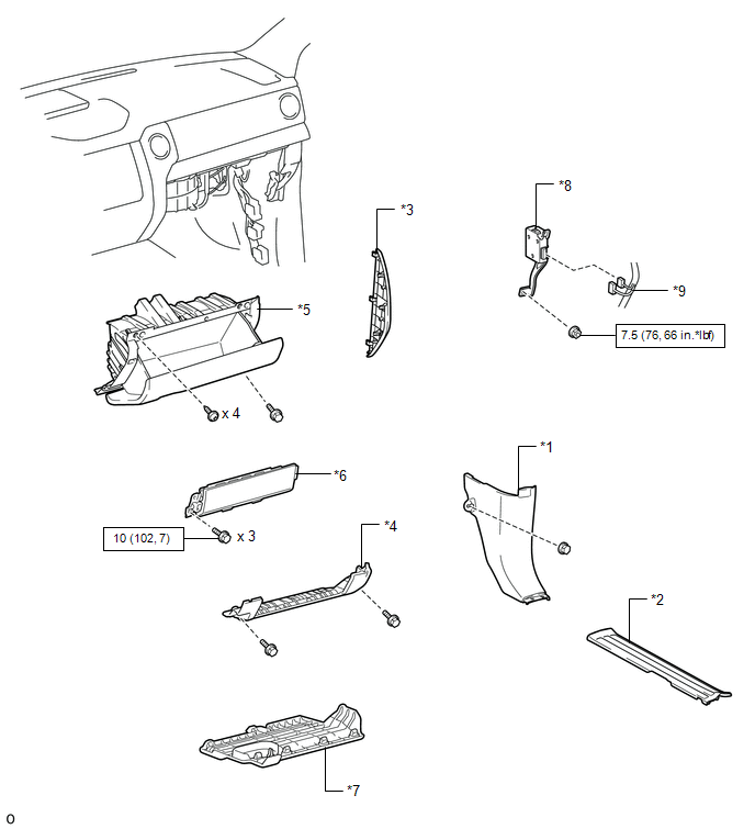
*1

COWL SIDE TRIM BOARD RH

*2

FRONT DOOR SCUFF PLATE RH

*3

INSTRUMENT SIDE PANEL RH

*4

LOWER INSTRUMENT PANEL

*5

LOWER INSTRUMENT PANEL FINISH PANEL SUB-ASSEMBLY RH

*6

LOWER NO. 2 INSTRUMENT PANEL AIRBAG ASSEMBLY

*7

NO. 2 INSTRUMENT PANEL UNDER COVER SUB-ASSEMBLY

*8

TRAILER BRAKE CONTROL ECU (BRAKE CONTROL WITH BRACKET RELAY)

*9

CONNECTOR

-

-

N*m (kgf*cm, ft.*lbf): Specified torque

-

-

    Trailer Brake Control Ecu

    Installation

    See More:

    Toyota Tundra Service Manual > Sfi System: Brake Switch "B" Circuit High (P0724)
    DESCRIPTION The purpose of this circuit is to prevent the engine from stalling while driving in the lock-up condition when the brakes are suddenly applied. When the brake pedal is depressed, this switch sends a signal to the ECM. Then the ECM cancels the operation of the lock-up clutch while braking ...

    Toyota Tundra Owners Manual

    Toyota Tundra Service Manual

    © 2025 Copyright www.ttundra.com
    0.0335