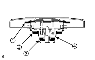
ON-VEHICLE INSPECTION PROCEDURE 1. INSPECT RADIATOR CAP SUB-ASSEMBLY CAUTION: To avoid the danger of being burned, do not remove the radiator cap while the engine and radiator are still hot, as fluid and steam can be blown out under pressure.  (a) Measure the valve opening pressure. (1) If there are water stains or foreign matter on rubber packing 1, 2 or 3, clean it by using water and finger scouring. (2) Check that rubber packing 1, 2 and 3 are not deformed, cracked or swollen. (3) Check that rubber packing 3 and 4 are not stuck together. (4) Apply engine coolant to rubber packing 2 and 3.
(6) Pump the cap tester several times, and check the maximum pressure*. Pumping speed: 1 pump per second HINT: *: Even if the cap cannot maintain the maximum pressure, it is not a defect. Standard Judgment Criterion:
If the maximum pressure is less than the minimum standard value, replace the radiator cap sub-assembly. 2. INSPECT FINS FOR BLOCKAGE (a) Check that the radiator and condenser are not blocked with leaves, dirt, or insects. Clean the hose connections. If the fins are blocked, wash them with water or a steam cleaner. NOTICE:
(b) Dry the fins with compressed air. |
Toyota Tundra Owners Manual > Using the driving support
systems: Intuitive parking assist
The distance from your vehicle to nearby obstacles when parallel parking or maneuvering into a garage is measured by the sensors and communicated via the multi-information display and buzzer. Always check the surrounding area when using this system. ■ Types of sensors Front corner sensors Rear co ...