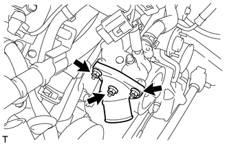
INSTALLATION PROCEDURE 1. INSTALL WATER INLET SUB-ASSEMBLY WITH THERMOSTAT
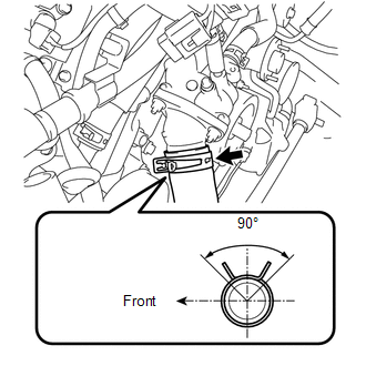
2. CONNECT OUTLET RADIATOR HOSE
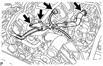
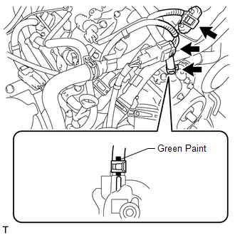
3. INSTALL AIR TUBE SUB-ASSEMBLY LH
(b) Connect the vacuum sensor connector and clamp.
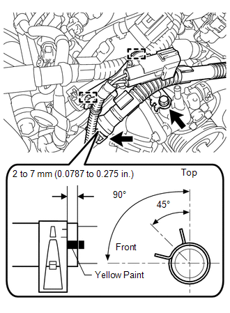
(d) Connect the air hose. (e) Connect the 2 wire harness clamps. HINT: When installing the hose, make sure the paint mark and clip are as shown in the illustration.
4. ADD ENGINE COOLANT 5. INSPECT FOR COOLANT LEAK 6. INSTALL AIR CLEANER ASSEMBLY 7. INSTALL V-BANK COVER SUB-ASSEMBLY 8. INSTALL NO. 1 ENGINE UNDER COVER |
Toyota Tundra Service Manual > Brake: Front Brake Flexible Hose
ComponentsCOMPONENTS ILLUSTRATION InstallationINSTALLATION CAUTION / NOTICE / HINT HINT: Use the same procedures for the LH side and RH side. The procedures listed below are for the LH side. PROCEDURE 1. INSTALL FRONT FLEXIBLE HOSE (a) Attach 2 new clips (labeled A) to the flexible hose. (b) Using ...