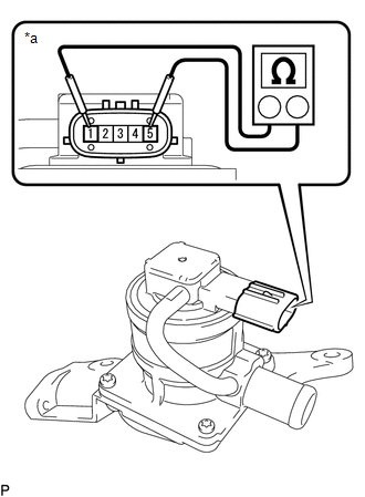
INSPECTION PROCEDURE 1. INSPECT AIR SWITCHING VALVE ASSEMBLY
(b) Check the operation of the air switching valve assembly. 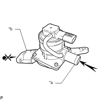 (1) Check that air does not flow from port A to port B. Text in Illustration
NOTICE: Make sure the applied pressure is 30 kPa (0.3 kgf/cm2, 4.4 psi) or less. If the result is not as specified, replace the air switching valve assembly. 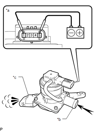 (2) Apply battery voltage across terminals 1 and 5. Text in Illustration
NOTICE: When applying voltage, do not touch terminals 2, 3 or 4. (3) Check that air flows from port A to port B. If the result is not as specified, replace the air switching valve assembly. |
Toyota Tundra Service Manual > Exterior: Front Door Belt Moulding(for Crewmax)
Components COMPONENTS ILLUSTRATION ILLUSTRATION Installation INSTALLATION CAUTION / NOTICE / HINT HINT: Use the same procedures for the RH side and LH side. The procedures listed below are for the LH side. PROCEDURE 1. INSTALL FRONT OUTER DOOR GLASS WEATHERSTRIP ASSEMBLY LH (a) Attach the claw to in ...