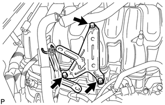
INSTALLATION PROCEDURE 1. INSTALL EGR VALVE BRACKET
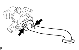
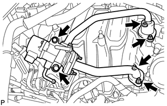
2. INSTALL NO. 3 EGR PIPE SUB-ASSEMBLY
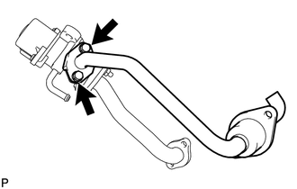
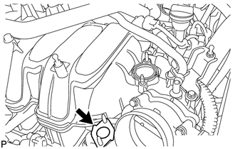
3. INSTALL EGR INLET
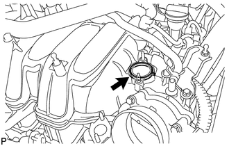
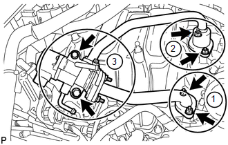
4. INSTALL EGR VALVE ASSEMBLY
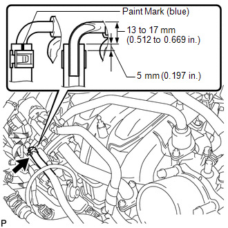
5. CONNECT NO. 13 WATER BY-PASS HOSE
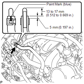
6. CONNECT NO. 12 WATER BY-PASS HOSE
7. INSTALL AIR CLEANER HOSE ASSEMBLY 8. ADD ENGINE COOLANT 9. INSPECT FOR ENGINE COOLANT LEAK 10. INSTALL V-BANK COVER SUB-ASSEMBLY |
Toyota Tundra Service Manual > Airbag System: Short in P/T Squib (LH) Circuit (B1905-B1908)
DESCRIPTION The front pretensioner LH circuit consists of the airbag sensor assembly and front seat outer belt assembly LH. This circuit instructs the SRS to deploy when deployment conditions are met. These DTCs are stored when a malfunction is detected in the front pretensioner LH circuit. DTC No. ...