Toyota Tundra Service Manual: Removal

REMOVAL

PROCEDURE

1. REMOVE V-BANK COVER SUB-ASSEMBLY

2. REMOVE AIR CLEANER HOSE ASSEMBLY

3. DRAIN ENGINE COOLANT

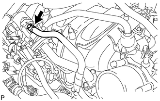
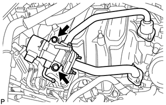
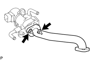
4. DISCONNECT NO. 12 WATER BY-PASS HOSE

(a) Disconnect the No. 12 water by-pass hose.

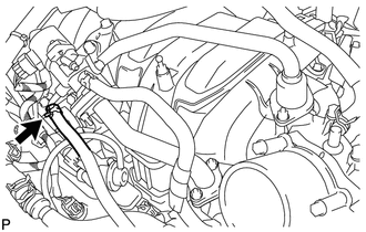
5. DISCONNECT NO. 13 WATER BY-PASS HOSE

(a) Disconnect the No. 13 water by-pass hose.

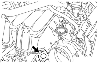
6. REMOVE EGR VALVE ASSEMBLY
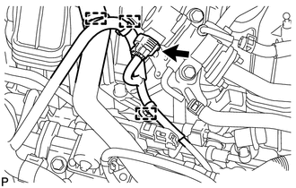
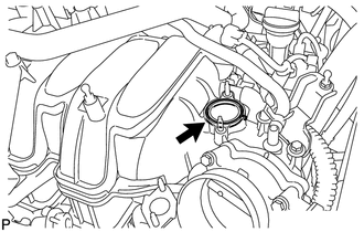
(a) Disconnect the 3 clamps and connector.

(b) Remove the 4 nuts.

(c) Remove the 2 bolts and EGR valve.

(d) Remove the gasket from the No. 2 EGR pipe.

NOTICE:

Be careful not to damage the installation surface of the gaskets.

(e) Remove the gasket from the intake manifold.

7. REMOVE EGR INLET

(a) Remove the 2 bolts, EGR inlet and gasket.

NOTICE:

Be careful not to damage the installation surface of the gaskets.

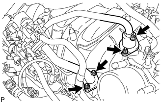
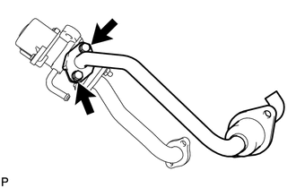
8. REMOVE NO. 3 EGR PIPE SUB-ASSEMBLY

(a) Remove the 2 nuts, No. 3 EGR pipe and gasket.

NOTICE:

Be careful not to damage the installation surface of the gaskets.

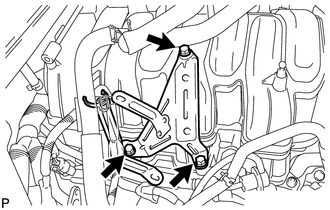
9. REMOVE EGR VALVE BRACKET

(a) Remove the 3 bolts and EGR valve bracket.

    Installation

    Emission Control System

    See More:

    Toyota Tundra Service Manual > Can Communication System: Lost Communication with Gateway Module (U1002)
    DESCRIPTION The main body ECU (multiplex network body ECU) stores this DTC when no signals can be received from the ECUs that have been memorized as those connected to the sub bus 1. When the main body ECU (multiplex network body ECU) receives a response signal from the ECUs connected to the sub bus ...

    Toyota Tundra Owners Manual

    Toyota Tundra Service Manual

    © 2026 Copyright www.ttundra.com
    0.0109