REMOVAL CAUTION / NOTICE / HINT CAUTION:
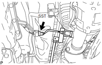
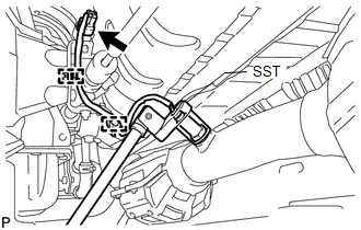
PROCEDURE 1. REMOVE PROPELLER SHAFT HEAT INSULATOR 2. REMOVE HEATED OXYGEN SENSOR (for Bank 1 Sensor 2) (a) Disconnect the heated oxygen sensor connector.
3. REMOVE HEATED OXYGEN SENSOR (for Bank 2 Sensor 2)
(b) Using SST, remove the heated oxygen sensor. SST: 09224-00010 |
Toyota Tundra Service Manual > Instrument Panel Safety Pad(for Column Shift Type): Removal
REMOVAL PROCEDURE 1. TABLE OF BOLT, SCREW AND NUT HINT: All bolts, screws and nuts relevant to installing and removing the instrument panel are shown along with their alphabet code below. 2. PRECAUTION NOTICE: After turning the ignition switch off, waiting time may be required before disconnecting t ...