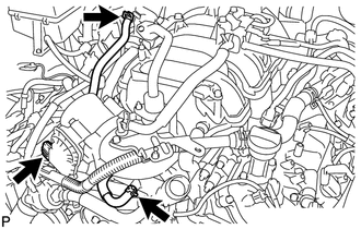
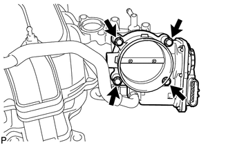
REMOVAL PROCEDURE 1. REMOVE NO. 1 ENGINE UNDER COVER 2. DRAIN ENGINE COOLANT 3. REMOVE V-BANK COVER SUB-ASSEMBLY 4. REMOVE AIR CLEANER HOSE ASSEMBLY 5. REMOVE THROTTLE BODY ASSEMBLY
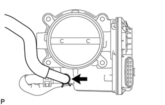
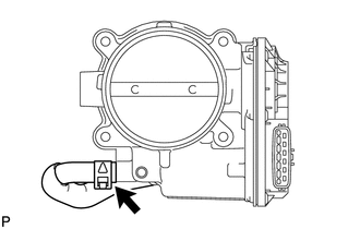
(b) Disconnect the throttle position sensor and control motor connector.
|
Toyota Tundra Service Manual > Front Camera: Installation
INSTALLATION PROCEDURE 1. INSTALL FORWARD RECOGNITION WITH HEATER HOOD SUB-ASSEMBLY NOTICE: Do not touch the internal components of the forward recognition with heater hood sub-assembly or press on the heater when working on the forward recognition with heater hood sub-assembly. Heater Area (a) Atta ...