INSTALLATION CAUTION / NOTICE / HINT HINT: Perform "Inspection After Repairs" after replacing the cylinder head sub-assembly LH (See page
PROCEDURE 1. INSPECT CYLINDER HEAD SET BOLT 2. INSPECT CYLINDER HEAD SUB-ASSEMBLY LH 3. INSTALL CYLINDER HEAD GASKET LH (a) Check the piston protrusions for each cylinder. (1) Clean the cylinder block with solvent. (2) Set the piston of the cylinder to be measured to slightly ATDC.
4. INSTALL CYLINDER HEAD SUB-ASSEMBLY LH HINT: Perform "Inspection After Repairs" after replacing the cylinder head sub-assembly LH (See page
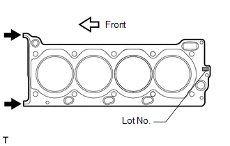
(a) Place the cylinder head on the cylinder block. NOTICE:
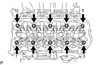
HINT: The cylinder head bolts are tightened in 3 progressive steps. (b) Apply a light coat of engine oil to the threads and under the heads of the cylinder head bolts.
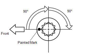
(e) Step 3: (1) Tighten the cylinder head bolts an additional 90° in the sequence shown in step 1. (2) Check that the painted marks are now facing rearward.
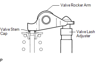
5. INSTALL VALVE STEM CAP (a) Apply a light coat of engine oil to the valve stem caps. (b) Install the 16 valve stem caps to the cylinder head. 6. INSTALL VALVE LASH ADJUSTER ASSEMBLY (a) Inspect the valve lash adjuster (See page (b) Install the 16 lash adjusters to the cylinder head. NOTICE: Install the lash adjuster at the same place it was removed from. 7. INSTALL NO. 1 VALVE ROCKER ARM SUB-ASSEMBLY (a) Apply engine oil to the lash adjuster tips and valve stem cap ends.
8. INSTALL CAMSHAFTS (for Bank 1) (a) Install the camshafts (See page
9. INSTALL EXHAUST MANIFOLD SUB-ASSEMBLY LH (a) Install the exhaust manifold LH (See page |
Toyota Tundra Service Manual > Theft Deterrent System: Security Horn Circuit
DESCRIPTION When the theft deterrent system is switched from the armed state to the alarm sounding state, the main body ECU (multiplex network body ECU) transmits a signal to cause the security horn to sound at intervals of 0.4 seconds. WIRING DIAGRAM CAUTION / NOTICE / HINT NOTICE: Inspect the fuse ...

 ).
).