REMOVAL PROCEDURE 1. REMOVE EXHAUST MANIFOLD SUB-ASSEMBLY LH (a) Remove the exhaust manifold LH (See page 2. REMOVE CAMSHAFTS (for Bank 1) (a) Remove the camshafts (See page
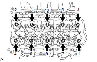
3. REMOVE NO. 1 VALVE ROCKER ARM SUB-ASSEMBLY (a) Remove the 16 valve rocker arms from the cylinder head. HINT: Arrange the removed parts in the correct order. 4. REMOVE VALVE LASH ADJUSTER ASSEMBLY (a) Remove the 16 valve lash adjusters from the cylinder head. HINT: Arrange the removed parts in the correct order. 5. REMOVE VALVE STEM CAP (a) Remove the 16 valve stem caps from the cylinder head. HINT: Arrange the removed parts in the correct order. 6. REMOVE CYLINDER HEAD SUB-ASSEMBLY LH
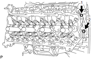
7. REMOVE CYLINDER HEAD GASKET LH |
Toyota Tundra Service Manual > Audio And Visual System: Speaker Output Short (B15C3)
DESCRIPTION This DTC is stored when a malfunction occurs in the speakers. DTC Code DTC Detection Condition Trouble Area B15C3 A short is detected in the speaker output circuit. Speakers Harness or connector Stereo component amplifier assembly Radio and display receiver assembly WIRING DIAGRAM PROCED ...

 ).
).