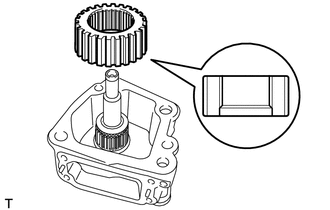
REASSEMBLY PROCEDURE 1. INSTALL STRAIGHT PIN
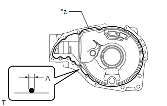
(a)
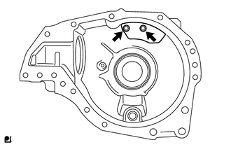
Using a plastic-faced hammer, tap in the straight pins until their
protrusion amounts are at the specified values shown in the illustration
below. 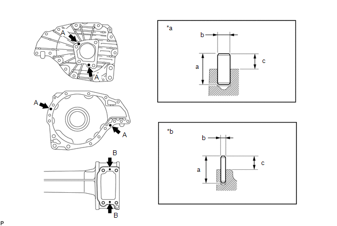 Standard depth: |
Item | a |
b | c | |
for Straight Pin A | 19.5 to 20.5 mm
(0.768 to 0.807 in.) |
9.991 to 10.000 mm (0.3934 to 0.3937 in.) |
9.5 to 10.0 mm (0.374 to 0.393 in.) | |
for Straight Pin B | 15.6 to 15.8 mm
(0.615 to 0.622 in.) |
3.995 to 4.000 mm (0.1574 to 0.3940 in.) |
5.6 to 6.2 mm (0.221 to 0.244 in.) | Text in Illustration |
*a | for Straight Pin A |
*b | for Straight Pin B |
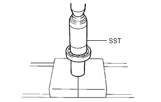
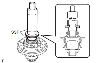
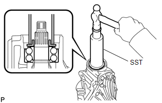
2. INSTALL FRONT DIFFERENTIAL SIDE GEAR SHAFT RH BEARING
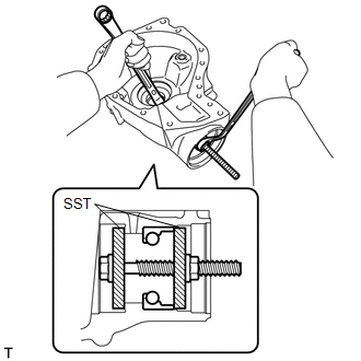
| (a) Using SST and a press, press in the bearing. SST: 09223-00010 |
|
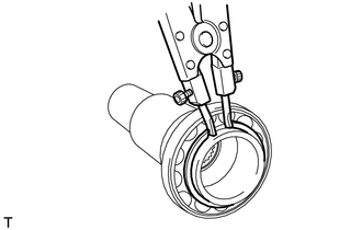
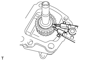
| (b) Using a snap ring expander, install a new snap ring. |
|
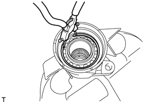
3. INSTALL DIFFERENTIAL SIDE GEAR SHAFT SUB-ASSEMBLY RH
| (a) Install the side gear shaft into the differential tube. |
|
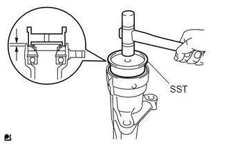
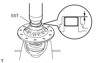
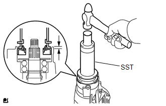
(b) Using snap ring pliers, install a new snap ring. 4. INSTALL DIFFERENTIAL SIDE GEAR SHAFT OIL SEAL
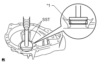
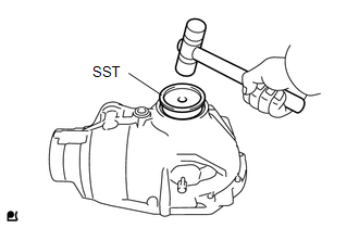
| (a) Using SST and a plastic-faced hammer, tap in a new oil seal.
SST: 09608-32010 Standard oil seal depth: 4.8 to 5.8 mm (0.189 to 0.228 in.) |
|
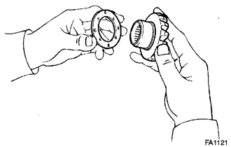
(b) Coat the lip of the oil seal with MP grease. 5. INSTALL DIFFERENTIAL CLUTCH HUB
| (a) Install the clutch hub onto the side gear inter shaft. |
|
| (b) Using snap ring pliers, install a new snap ring. NOTICE:
Be sure to install the differential clutch hub in the correct direction. |
|
(c) Install the differential clutch sleeve to the side gear shaft. 6. INSTALL FRONT DIFFERENTIAL SIDE GEAR NEEDLE ROLLER BEARING
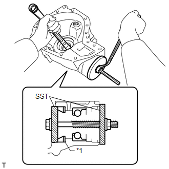
| (a) Using SST and a press, press in 2 new bearings. SST: 09950-60010
09951-00420 Standard bearing depth: 1.2 to 1.8 mm (0.0473 to 0.0708 in.) |
|
7. INSTALL FRONT DIFFERENTIAL CASE
| (a) Install the 2 side gear thrust washers onto the 2 side gears.
HINT: Using the table below, select the thrust washer which will ensure that the backlash is within the specifications.
Washer thickness: |
Thickness | Thickness | |
1.43 to 1.47 mm (0.0563 to 0.0578 in.) |
1.68 to 1.72 mm (0.0662 to 0.0677 in.) | |
1.48 to 1.52 mm (0.0583 to 0.0598 in.) |
1.73 to 1.77 mm (0.0682 to 0.0696 in.) | |
1.53 to 1.57 mm (0.0603 to 0.0618 in.) |
1.78 to 1.82 mm (0.0701 to 0.0716 in.) | |
1.58 to 1.62 mm (0.0622 to 0.0637 in.) |
1.83 to 1.87 mm (0.0721 to 0.0736 in.) | |
1.63 to 1.67 mm (0.0642 to 0.0657 in.) |
- | | |
(b)
Install the 2 side gears, 2 side gear thrust washers, 2 pinion gears, 2
pinion gear thrust washers and pinion shaft into the differential case
assembly.
HINT:
- Align the holes of the differential case assembly and pinion shaft.
- Apply hypoid gear oil to each sliding surface and rotating part.
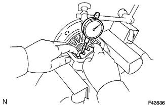
(c) Measure the side gear backlash.
| (1) Using a dial indicator, measure the side gear backlash while holding one pinion gear toward the differential case assembly.
Standard backlash: 0.1 to 0.25 mm (0.00394 to 0.00984 in.)
If the backlash is not within the specification, install a side gear thrust washer with a different thickness. |
|
| (d) Using a pin punch and hammer, tap in the straight pin through the differential case and hole of the pinion shaft. |
|
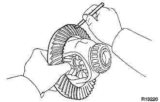
(e) Stake the differential case. 8. INSTALL DIFFERENTIAL RING GEAR
(a) Clean the contact surfaces of the differential case and ring gear.
(b) Heat the ring gear to about 100°C (212°F) in boiling water. (c) Carefully take the ring gear out of the boiling water.
(d) After the moisture on the ring gear has completely evaporated, quickly set the ring gear onto the differential case.
HINT:
- Align the matchmarks on the ring gear and differential case.
- Temporarily install the 12 bolts so that the bolt holes in the ring gear and differential case are aligned.
(e) After the ring gear cools down sufficiently, apply adhesive to the bolts and install them.
Torque: 137 N·m {1397 kgf·cm, 101 ft·lbf} Adhesive: Toyota Genuine Adhesive 1360K, Three Bond 1360K or equivalent
9. INSTALL FRONT DIFFERENTIAL CASE BEARING
| (a) Using SST and a press, press in the 2 bearings (inner race).
SST: 09316-20011 SST: 09316-60011 09316-00041 |
|
10. INSTALL FRONT DIFFERENTIAL CASE BEARING HINT: When
replacing the 2 differential case bearings, fit the thinnest washer to
each bearing. When reusing the bearings, fit a washer of the same
thickness as the one removed to each bearing.
| (a) Install a new plate washer to the bearing retainer. Text in Illustration |
|
(b) Using SST and a press, install the bearing (outer race) onto the bearing retainer.
SST: 09950-60020 09951-00890 SST: 09950-70010 09951-07150
| (c) Install a new plate washer onto the differential carrier. Text in Illustration |
|
(d) Using SST and a press, press in the bearing (outer race) onto the differential carrier assembly.
SST: 09950-60020 09951-00890 SST: 09950-70010 09951-07150
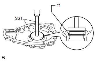
11. INSTALL FRONT DRIVE PINION FRONT RADIAL BALL BEARING
| (a) Using SST, install the bearing (outer race). SST: 09950-60020
09951-00810 09951-00890 | |
12. INSTALL FRONT DRIVE PINION REAR TAPERED ROLLER BEARING
| (a) Using SST, install the washer and bearing (outer race). SST: 09950-60020
09951-00890 09951-01030 Text in Illustration
HINT: First,
fit a washer of the same thickness as the removed washer, then after
checking the tooth contact pattern, replace the washer with one of a
different thickness if necessary. | |
13. INSTALL FRONT DIFFERENTIAL BREATHER PLUG OIL DEFLECTOR
| (a) Install the front differential breather plug oil deflector with the 2 bolts.
Torque: 6.0 N·m {61 kgf·cm, 53 in·lbf} | |
14. INSTALL FRONT DRIVE PINION REAR TAPERED ROLLER BEARING
| (a) Using SST and a press, press in the bearing (inner race).
SST: 09506-35010 | |
15. TEMPORARILY INSTALL DIFFERENTIAL DRIVE PINION 16. INSTALL FRONT DRIVE PINION FRONT RADIAL BALL BEARING
| (a) Using SST and a hammer, lightly tap in the bearing (inner race) to install it.
SST: 09316-60011 09316-00041 | |
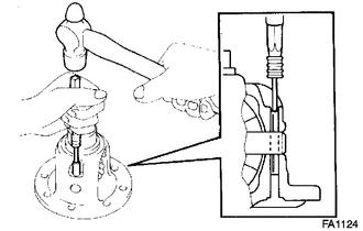
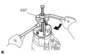
17. INSTALL FRONT DIFFERENTIAL DRIVE PINION OIL SLINGER 18. INSPECT DIFFERENTIAL DRIVE PINION PRELOAD
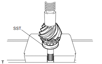
| (a) Using SST, install the companion flange. SST: 09950-30012
09951-03010 09953-03010 09954-03010 09955-03030
09956-03020 Text in Illustration |
|
(b) Coat the threads of the nut with hypoid gear oil LSD.
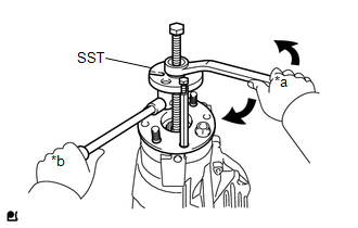
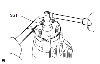
| (c) Using SST to hold the companion flange. SST: 09330-00021
09330-00030 | |
(d) Tighten the nut until the standard preload is reached. Torque:
451 N·m {4599 kgf·cm, 333 ft·lbf} or less NOTICE: As there is no spacer, tighten the nut a little at a time, being careful not to overtighten it.
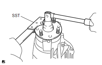
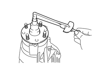
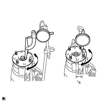
| (e) Using a torque wrench, measure the preload of the backlash between the drive pinion and ring gear.
Standard preload (at starting): |
Bearing | Specified Condition | |
New | 2.69 to 3.19 N*m (28 to 32 kgf*cm, 24 to 28 in.*lbf) | |
Reused | 1.86 to 2.17 N*m (19 to 22 kgf*cm, 17 to 19 in.*lbf) |
If necessary, disassemble and inspect the differential assembly. |
|
19. INSTALL FRONT DIFFERENTIAL CASE (a) Remove the bearing retainer.
(b) Install the differential case to the differential carrier. 20. INSTALL FRONT DIFFERENTIAL CROSS SHAFT BEARING RETAINER
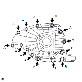
| (a) Install the differential cross shaft bearing retainer and differential support with the 14 bolts.
Torque: for bolt A : 65 N·m {663 kgf·cm, 48 ft·lbf}
for bolt B : 155 N·m {1581 kgf·cm, 114 ft·lbf} | |
21. INSTALL FRONT DIFFERENTIAL UNION
| (a) Install the front differential union. | |
22. ADJUST BACKLASH BETWEEN DIFFERENTIAL RING GEAR AND DIFFERENTIAL DRIVE PINION
| (a) Using SST and a dial indicator, measure the ring gear backlash.
SST: 09564-33010 Standard backlash: 0.17 to 0.27 mm (0.00670 to 0.01062 in.)
If
the backlash is not within the specification, adjust it by either
increasing or decreasing the thickness of the washers on both sides by
an equal amount.
HINT:
- There should be no clearance between the plate washer and differential case.
- Make sure that there is ring gear backlash.
Washer thickness: |
Thickness | Thickness | |
1.49 to 1.51 mm (0.0587 to 0.0594 in.) |
1.93 to 1.95 mm (0.0760 to 0.0767 in.) | |
1.51 to 1.53 mm (0.0595 to 0.0602 in.) |
1.95 to 1.97 mm (0.0768 to 0.0775 in.) | |
1.53 to 1.55 mm (0.0603 to 0.0610 in.) |
1.97 to 1.99 mm (0.0776 to 0.0783 in.) | |
1.55 to 1.57 mm (0.0611 to 0.0618 in.) |
1.99 to 2.01 mm (0.0784 to 0.0791 in.) | |
1.57 to 1.59 mm (0.0619 to 0.0625 in.) |
2.01 to 2.03 mm (0.0792 to 0.0799 in.) | |
1.59 to 1.61 mm (0.0626 to 0.0633 in.) |
2.03 to 2.05 mm (0.0800 to 0.0807 in.) | |
1.61 to 1.63 mm (0.0634 to 0.0641 in.) |
2.05 to 2.07 mm (0.0808 to 0.0814 in.) | |
1.63 to 1.65 mm (0.0642 to 0.0649 in.) |
2.07 to 2.09 mm (0.0815 to 0.0822 in.) | |
1.65 to 1.67 mm (0.0650 to 0.0657 in.) |
2.09 to 2.11 mm (0.0823 to 0.0830 in.) | |
1.67 to 1.69 mm (0.0658 to 0.0665 in.) |
2.11 to 2.13 mm (0.0831 to 0.0838 in.) | |
1.69 to 1.71 mm (0.0666 to 0.0673 in.) |
2.13 to 2.15 mm (0.0839 to 0.0846 in.) | |
1.71 to 1.73 mm (0.0674 to 0.0681 in.) |
2.15 to 2.17 mm (0.0847 to 0.0854 in.) | |
1.73 to 1.75 mm (0.0682 to 0.0688 in.) |
2.17 to 2.19 mm (0.0855 to 0.0862 in.) | |
1.75 to 1.77 mm (0.0689 to 0.0696 in.) |
2.19 to 2.21 mm (0.0863 to 0.0870 in.) | |
1.77 to 1.79 mm (0.0697 to 0.0704 in.) |
2.21 to 2.23 mm (0.0871 to 0.0877 in.) | |
1.79 to 1.81 mm (0.0705 to 0.0712 in.) |
2.23 to 2.25 mm (0.0878 to 0.0885 in.) | |
1.81 to 1.83 mm (0.0713 to 0.0720 in.) |
2.25 to 2.27 mm (0.0886 to 0.0893 in.) | |
1.83 to 1.85 mm (0.0721 to 0.0728 in.) |
2.27 to 2.29 mm (0.0894 to 0.0901 in.) | |
1.85 to 1.87 mm (0.0729 to 0.0736 in.) |
2.29 to 2.31 mm (0.0902 to 0.0909 in.) | |
1.87 to 1.89 mm (0.0737 to 0.0744 in.) |
2.31 to 2.33 mm (0.0910 to 0.0917 in.) | |
1.89 to 1.91 mm (0.0745 to 0.0751 in.) |
2.33 to 2.35 mm (0.0918 to 0.0925 in.) | |
1.91 to 1.93 mm (0.0752 to 0.0759 in.) |
- | | |
23. INSPECT TOTAL PRELOAD
| (a) Using a torque wrench, measure the preload with the teeth of the drive pinion and ring gear in contact.
Standard Drive Pinion Preload Plus: |
Bearing | Specified Condition | |
New | 4.30 to 5.60 N*m (44 to 57 kgf*cm, 39 to 49 in.*lbf) | |
Reused | 3.19 to 4.30 N*m (33 to 43 kgf*cm, 29 to 38 in.*lbf) |
NOTICE: Record the differential ring gear preload. If necessary, disassemble and inspect the differential. |
|
24. INSPECT TOOTH CONTACT BETWEEN RING GEAR AND DRIVE PINION (a) Remove the bearing retainer and differential case.
| (b) Coat 3 or 4 teeth at 3 different positions on the ring gear with Prussian blue. |
|
(c) Install the differential case to the differential carrier.
| (d) Install the differential cross shaft bearing retainer and front differential front support assembly LH with the 14 bolts.
Torque: for bolt A : 65 N·m {663 kgf·cm, 48 ft·lbf}
for bolt B : 155 N·m {1581 kgf·cm, 114 ft·lbf} | |
(e) Hold the companion flange firmly and rotate the ring gear in both directions.
(f) Remove the differential case, side bearing retainer and differential case.
(g) Inspect the tooth contact pattern.
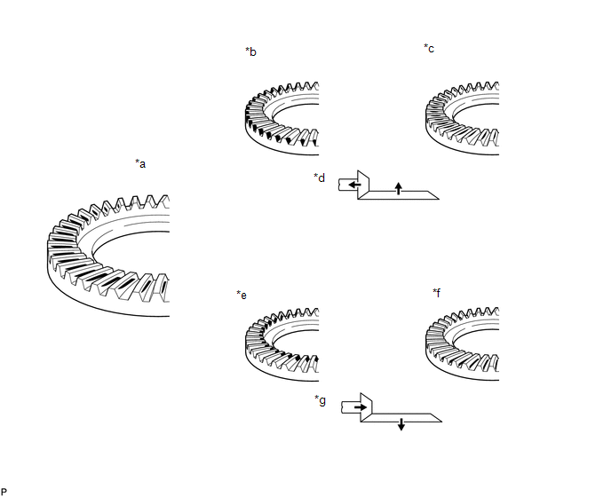 Text in Illustration Text in Illustration |
*a | Proper Contact |
*b | Heel Contact | |
*c | Face Contact |
*d | Select an adjusting washer that will shift the drive pinion closer to the ring gear (*b, *c) | |
*e | Toe Contact |
*f | Flank Contact | |
*g | Select an adjusting washer that will shift the drive pinion away from the ring gear (*e, *f) |
- | - |
If the teeth are not engaged properly, use the following chart to select the appropriate washer for correction.
Washer thickness: |
Thickness | Thickness | |
1.815 to 1.835 mm (0.0715 to 0.0722 in.) |
2.065 to 2.085 mm (0.0813 to 0.0820 in.) | |
1.840 to 1.860 mm (0.0725 to 0.0732 in.) |
2.090 to 2.110 mm (0.0823 to 0.0830 in.) | |
1.865 to 1.885 mm (0.0735 to 0.0742 in.) |
2.115 to 2.135 mm (0.0833 to 0.0840 in.) | |
1.890 to 1.910 mm (0.0744 to 0.0751 in.) |
2.140 to 2.160 mm (0.0843 to 0.0850 in.) | |
1.915 to 1.935 mm (0.0754 to 0.0761 in.) |
2.165 to 2.185 mm (0.0853 to 0.0860 in.) | |
1.940 to 1.960 mm (0.0764 to 0.0771 in.) |
2.190 to 2.210 mm (0.0863 to 0.0870 in.) | |
1.965 to 1.985 mm (0.0774 to 0.0781 in.) |
2.215 to 2.235 mm (0.0872 to 0.0879 in.) | |
1.990 to 2.010 mm (0.0784 to 0.0791 in.) |
2.240 to 2.260 mm (0.0882 to 0.0889 in.) | |
2.015 to 2.035 mm (0.0794 to 0.0801 in.) |
2.265 to 2.285 mm (0.0892 to 0.0899 in.) | |
2.040 to 2.060 mm (0.0804 to 0.0811 in.) |
- | 25. REMOVE FRONT DRIVE PINION COMPANION FLANGE FRONT NUT
 26. REMOVE FRONT DRIVE PINION FRONT COMPANION FLANGE SUB-ASSEMBLY
27. REMOVE FRONT DIFFERENTIAL DRIVE PINION OIL SLINGER
28. REMOVE FRONT DIFFERENTIAL CROSS SHAFT BEARING RETAINER
29. REMOVE FRONT DIFFERENTIAL CASE
30. REMOVE DIFFERENTIAL DRIVE PINION
31. REMOVE FRONT DRIVE PINION FRONT RADIAL BALL BEARING
32. INSTALL FRONT DIFFERENTIAL DRIVE PINION BEARING SPACER (a) Install a new bearing spacer.
33. TEMPORARILY INSTALL DIFFERENTIAL DRIVE PINION 34. INSTALL FRONT DIFFERENTIAL CASE
35. INSTALL FRONT DIFFERENTIAL CROSS SHAFT BEARING RETAINER
| (a)
Remove any old FIPG material and be careful not to drop oil on the
contact surfaces of the differential carrier and side bearing retainer. Text in Illustration |
|
(b) Clean the contact surfaces with any residual FIPG material using gasoline or alcohol.
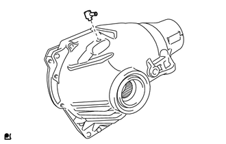
(c) Apply seal packing to the differential carrier as shown in the illustration.
Seal packing: Toyota Genuine Seal Packing 1281, Three Bond 1281 or equivalent
Standard Seal Diameter (A): 2.0 to 3.0 mm (0.0788 to 0.118 in.)
HINT: Install the side bearing retainer within 10 minutes of applying seal packing.
| (d)
Install the front differential cross shaft bearing retainer and front
differential front support assembly LH with the 11 bolts (A), and 3
bolts (B). Torque: for bolt A : 65 N·m {663 kgf·cm, 48 ft·lbf}
for bolt B : 155 N·m {1581 kgf·cm, 114 ft·lbf} NOTICE:
Do
not add oil or drive the vehicle immediately after installing the
cover, and leave it as is for at least an hour. Also, for 12 hours or
less, avoid rapid acceleration/deceleration. | |
36. INSTALL FRONT DRIVE PINION FRONT RADIAL BALL BEARING
| (a) Using SST and a hammer, lightly tap in the bearing (inner race) to install it.
SST: 09316-60011 09316-00041 | |
37. INSTALL FRONT DIFFERENTIAL DRIVE PINION OIL SLINGER 38. INSTALL FRONT DIFFERENTIAL CARRIER OIL SEAL
| (a) Using SST and a hammer, tap in a new oil seal. SST: 09502-12010
SST: 09316-60011 09316-00041 Standard oil seal depth:
5.6 to 6.6 mm (0.221 to 0.259 in.) | |
(b) Coat the lip of the oil seal with MP grease. 39. INSTALL FRONT DRIVE PINION COMPANION FLANGE SUB-ASSEMBLY
| (a) Using SST, install the companion flange. SST: 09950-30012
09951-03010 09953-03010 09954-03010 09955-03030
09956-03020 Text in Illustration |
|
| (b) Using SST to hold the companion flange. SST: 09330-00021
09330-00030 | |
(c) Coat the threads of a new nut with hypoid gear oil LSD. (d) Install the nut by tightening it until the standard preload is reached.
Torque: 451 N·m {4599 kgf·cm, 333 ft·lbf} or less
| (e) Using a torque wrench, measure the preload of the backlash between the drive pinion and ring gear.
Standard total preload (at starting): |
Bearing | Specified Condition | |
New | 3.05 to 3.55 N*m (32 to 36 kgf*cm, 27 to 31 in.*lbf) | |
Reused | 2.22 to 2.53 N*m (23 to 25 kgf*cm, 20 to 22 in.*lbf) |
If the preload is more than the specification, replace the bearing spacer.
If
the preload is less than the specification, tighten the nut with 13 N*m
(130 kgf*cm, 9 ft.*lbf) of torque at a time until the specified preload
is reached. Torque: 451 N·m {4599 kgf·cm, 333 ft·lbf} or less
If the maximum torque is exceeded while tightening the nut, replace the bearing spacer and repeat the preload procedure.
HINT: Do not loosen the nut to reduce the preload. | |
40. INSPECT TOTAL PRELOAD
| (a) With the drive pinion contacting the tooth side of the ring gear, use a torque wrench to measure the total preload.
Standard total preload (at starting): |
Bearing | Specified Condition | |
New | 4.66 to 5.96 N*m (48 to 60 kgf*cm, 42 to 52 in.*lbf) | |
Reused | 3.55 to 4.66 N*m (37 to 47 kgf*cm, 32 to 41 in.*lbf) | |
|
41. INSPECT BACKLASH BETWEEN DIFFERENTIAL RING GEAR AND DIFFERENTIAL DRIVE PINION
| (a) Using SST and a dial indicator, measure the ring gear backlash.
SST: 09564-33010 Standard backlash: 0.17 to 0.27 mm (0.00670 to 0.0106 in.) |
|
42. INSPECT RUNOUT OF FRONT DRIVE PINION COMPANION FLANGE SUB-ASSEMBLY
| (a) Using a dial indicator, measure the runout of the companion flange vertically and laterally. Text in Illustration
Maximum runout: |
Runout | Specified Condition | |
Vertical runout | 0.10 mm (0.00394 in.) | |
Lateral runout | 0.10 mm (0.00394 in.) |
If the runout is more than the maximum, replace the companion flange. |
|
43. STAKE FRONT DRIVE PINION COMPANION FLANGE FRONT NUT
| (a) Using a chisel and hammer, stake the nut. | |
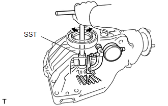
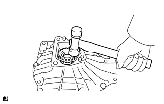
44. INSTALL DIFFERENTIAL SIDE GEAR SHAFT OIL SEAL
| (a) Using SST and a plastic-faced hammer, tap in a new oil seal until its surface is flush with the differential carrier end.
SST: 09608-32010 | |
(b) Coat the lip of the oil seal with MP grease. Standard oil seal depth:
-0.45 to 0.45 mm (-0.0177 to 0.0177 in.) 45. INSTALL DIFFERENTIAL SIDE GEAR INTER SHAFT SUB-ASSEMBLY
| (a) Install a new snap ring onto the side gear inter shaft. |
|
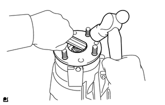
(b) Using a plastic-faced hammer, install the side gear inter shaft onto the differential case.
(c) Check that there is 2 to 3 mm (0.0788 to 0.118 in.) of play in the axial direction.
(d) Check that the side gear inter shaft does not come out when trying to pull it out by hand.
46. INSTALL FRONT DIFFERENTIAL TUBE ASSEMBLY
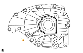
| (a)
Remove any old FIPG material and be careful not to drop oil on the
contact surfaces of the differential tube and bearing retainer. Text in Illustration |
|
(b) Clean the contact surfaces with any residual FIPG material using gasoline or alcohol.
(c) Apply seal packing to the bearing retainer as shown in the illustration.
Seal packing: Toyota Genuine Seal Packing 1281, Three Bond 1281 or equivalent
HINT: Install the differential tube within 10 minutes of applying seal packing.
(d) Install the differential tube onto the bearing retainer.
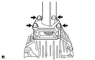
| (e) Clean the threads of 4 new bolts and the retainer bolt holes with toluene or trichloroethylene. |
|
(f) Apply adhesive to 2 to 3 threads of each bolt end. Adhesive:
Toyota Genuine Adhesive 1324, Three Bond 1324 or equivalent (g) Install the 4 bolts.
Torque: 65 N·m {663 kgf·cm, 48 ft·lbf} NOTICE: Do
not add oil or drive the vehicle immediately after installing the
cover, and leave it as is for at least an hour. Also, for 12 hours or
less, avoid rapid acceleration/deceleration. 47. INSPECT DIFFERENTIAL VACUUM ACTUATOR ASSEMBLY
(See page ) 48. INSTALL DIFFERENTIAL VACUUM ACTUATOR ASSEMBLY
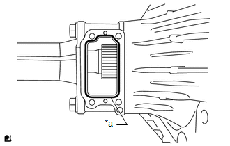
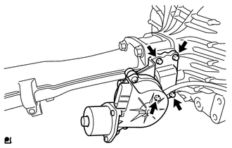
| (a) Remove any old FIPG material and be careful not to drop oil on the contact surfaces of the differential tube and actuator. Text in Illustration |
|
(b) Clean the contact surfaces with any residual FIPG material using gasoline or alcohol.
(c) Apply seal packing to the differential tube as shown in the illustration.
Seal packing: Toyota Genuine Seal Packing 1281, Three Bond 1281 or equivalent
HINT: Install the actuator within 10 minutes of applying seal packing.
| (d) Clean the threads of the 4 bolts and retainer bolt holes with toluene or trichloroethylene. |
|
(e) Install the actuator to the differential tube. (f) Install the 4 bolts.
Torque: 21 N·m {210 kgf·cm, 15 ft·lbf} |