INSTALLATION CAUTION / NOTICE / HINT HINT:
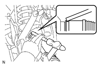
PROCEDURE 1. INSTALL FRONT DRIVE SHAFT ASSEMBLY LH (for Front Differential Side) (a) Install a new snap ring to the inboard joint shaft. (b) Coat the spline of the inboard joint shaft assembly with gear oil.
2. INSTALL FRONT DRIVE SHAFT ASSEMBLY LH (for Axle Hub Side) (a) Install the drive shaft to the steering knuckle. NOTICE: Be careful not to damage the oil seal, boots and dust seal. 3. CONNECT FRONT LOWER BALL JOINT ATTACHMENT
4. INSTALL TIE ROD END SUB-ASSEMBLY 5. INSTALL AXLE HUB NUT
6. INSTALL FRONT AXLE HUB GREASE CAP 7. INSTALL FRONT SPEED SENSOR LH (a) Install the front speed sensor (see page 8. INSTALL NO. 1 ENGINE UNDER COVER 9. INSTALL FRONT WHEEL (a) Install the front wheels. Torque: for aluminum wheel : 131 N·m {1336 kgf·cm, 97 ft·lbf} for steel wheel : 209 N·m {2131 kgf·cm, 154 ft·lbf} 10. ADD DIFFERENTIAL OIL 11. CHECK SPEED SENSOR SIGNAL (a) Check the speed sensor signal (see page 12. CHECK FOR DIFFERENTIAL OIL LEAK 13. INSPECT AND ADJUST FRONT WHEEL ALIGNMENT (a) Inspect and adjust the front wheel alignment (see page
|
Toyota Tundra Service Manual > Roof Headlining(for Crewmax): Removal
REMOVAL PROCEDURE 1. LOWER BACK WINDOW GLASS HINT: Make sure to completely lower the back window glass so that the roof headlining can be removed from the rear of the vehicle. 2. PRECAUTION NOTICE: After turning the ignition switch off, waiting time may be required before disconnecting the cable fro ...

 ).
).