REASSEMBLY PROCEDURE 1. INSTALL FRONT NO. 1 SPRING BUMPER LH (a) Install the No. 1 spring bumper to the vehicle. Torque: 31 N·m {316 kgf·cm, 23 ft·lbf} 2. INSTALL FRONT NO. 2 LOWER ARM LH 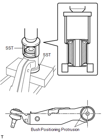 (a) Using SST and a press, press in a new bush. SST: 09710-26011 09710-05081 NOTICE: Press the bush while making sure the bush positioning protrusions are perpendicular to the lower arm, as shown in the illustration. 3. INSTALL FRONT NO. 1 LOWER ARM BUSH LH 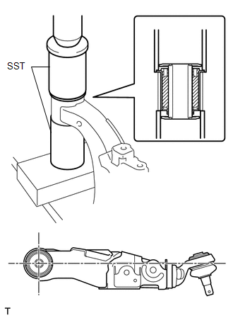 (a) Using SST and a press, press in a new bush. SST: 09223-00010 SST: 09612-30012 4. INSTALL FRONT LOWER BALL JOINT ATTACHMENT LH (a) Install the attachment with the nut and a new cotter pin. Torque: 167 N·m {1703 kgf·cm, 123 ft·lbf} NOTICE: If the holes for the cotter pin are not aligned, tighten the nut further up to 60°. |
Toyota Tundra Service Manual > Navigation System: Noise Occurs
PROCEDURE 1. NOISE CONDITION (a) Check from which direction the noise comes (front left or right, or rear left or right). OK: The location of the noise source can be determined. NG GO TO STEP 3 OK 2. CHECK SPEAKERS (a) Check the installation conditions of the speaker units that are located near the ...


