
INSTALLATION CAUTION / NOTICE / HINT HINT:
PROCEDURE 1. TEMPORARILY INSTALL FRONT SUSPENSION UPPER ARM ASSEMBLY LH 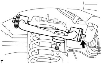 (a) Temporarily install the suspension upper arm with the 2 washers, bolt and nut. HINT: After stabilizing the suspension, tighten the nut. 2. INSTALL FRONT FENDER APRON SEAL REAR LH (a) Install the apron seal with the 5 clips. 3. INSTALL FRONT FENDER APRON SEAL LH (a) Install the apron seal with the 6 clips. 4. CONNECT STEERING KNUCKLE LH (a) Connect the steering knuckle to the suspension upper arm. (b) Install the nut and a new cotter pin. Torque: 110 N·m {1122 kgf·cm, 81 ft·lbf} NOTICE: If the holes for the cotter pin are not aligned, tighten the nut further up to 60°. 5. CONNECT SKID CONTROL SENSOR WIRE 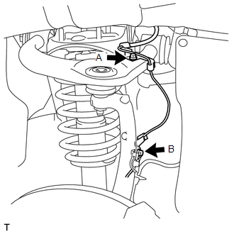 (a) Connect the sensor wire to the steering knuckle and upper arm with the 2 bolts. Torque: for Bolt A : 13 N·m {133 kgf·cm, 10 ft·lbf} for Bolt B : 29 N·m {296 kgf·cm, 21 ft·lbf} 6. TEMPORARILY INSTALL FRONT SHOCK ABSORBER WITH COIL SPRING LH 7. STABILIZE SUSPENSION
8. TIGHTEN FRONT SUSPENSION UPPER ARM ASSEMBLY LH (a) Tighten the nut. Torque: 235 N·m {2396 kgf·cm, 173 ft·lbf} 9. TIGHTEN FRONT SHOCK ABSORBER WITH COIL SPRING
10. INSPECT AND ADJUST FRONT WHEEL ALIGNMENT (a) Inspect and adjust the front wheel alignment (see page
11. INSTALL FRONT WHEEL Torque: for Aluminum Wheel : 131 N·m {1336 kgf·cm, 97 ft·lbf} for Steel Wheel : 209 N·m {2131 kgf·cm, 154 ft·lbf} |
Toyota Tundra Service Manual > Outer Rear View Mirror: Removal
REMOVAL CAUTION / NOTICE / HINT HINT: Use the same procedure for the RH and LH sides. The procedure listed below is for the LH side. PROCEDURE 1. REMOVE FRONT DOOR INSIDE HANDLE BEZEL PLUG 2. REMOVE FRONT UPPER ARMREST BASE PANEL LH 3. REMOVE FRONT LOWER DOOR FRAME BRACKET GARNISH 4. REMOVE FRONT DO ...

 ).
).

