DESCRIPTION |
DTC No. | DTC Detection Condition |
Trouble Area | | U0208 |
There is no communication from the front power seat switch LH (power seat control ECU). |
- Front power seat switch LH (power seat control ECU) CAN branch wire or connector
- Power source or inside of front power seat switch LH (power seat control ECU)
- Front power seat switch LH (power seat control ECU) ground circuit
- Front power seat switch LH (power seat control ECU)
| WIRING DIAGRAM
 CAUTION / NOTICE / HINT
CAUTION: When performing the confirmation driving pattern, obey all speed limits and traffic laws.
NOTICE:
HINT:
- Operating the ignition switch, any switches or any doors triggers
related ECU and sensor communication with the CAN, which causes
resistance variation.
- Even after DTCs are cleared, if a DTC is stored again after driving the
vehicle for a while, the malfunction may be occurring due to vibration
of the vehicle. In such a case, wiggling the ECUs or wire harness while
performing the inspection below may help determine the cause of the
malfunction.
PROCEDURE (a) Reconfirm DTCs.
HINT: If
DTC U1002 is output from Gateway of the main body ECU (multiplex
network body ECU), this indicates a sub bus 1 malfunction. Troubleshoot
for DTC U1002 and check for malfunctions in sub bus 1. Result |
Result | Proceed to | |
DTC U1002 is not output from main body ECU (multiplex network body ECU). |
A | | DTC U1002 is output from main body ECU (multiplex network body ECU). |
B |
| B |
 | GO TO DIAGNOSIS PROCEDURE INDICATED BY OUTPUT DTC |
|
A |
 | |
| 2. |
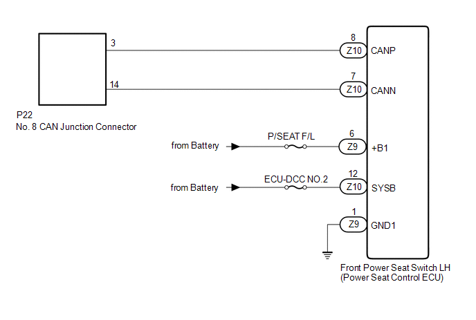
CHECK FOR OPEN IN CAN BUS WIRE (FRONT POWER SEAT SWITCH LH [Power Seat Control ECU] CAN BRANCH WIRE) |
(a) Disconnect the cable from the negative (-) battery terminal.
| (b) Disconnect the front power seat switch LH (power seat control ECU) connector. |
 |
|
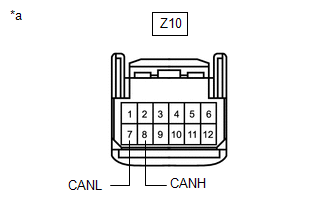
*a | Front view of wire harness connector
(to Front Power Seat Switch LH [Power Seat Control ECU]) | | |
(c) Measure the resistance according to the value(s) in the table below.
Standard Resistance: |
Tester Connection | Condition |
Specified Condition | |
Z10-8 (CANH) - Z10-7 (CANL) |
Cable disconnected from negative (-) battery terminal |
54 to 69 Ω |
| NG |
| REPAIR OR REPLACE FRONT POWER SEAT SWITCH LH CAN BRANCH WIRE OR CONNECTOR |
|
OK | |
| |
| 3. |
CHECK HARNESS AND CONNECTOR (POWER SOURCE CIRCUIT) |
| (a) Disconnect the front power seat switch LH (power seat control ECU) connector. |
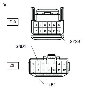 |
|
*a | Front view of wire harness connector
(to Front Power Seat Switch [Power Seat Control ECU]) | | |
(b) Measure the resistance according to the value(s) in the table below.
Standard Resistance: |
Tester Connection | Condition |
Specified Condition | |
Z9-2 (GND1) - Body ground |
Cable disconnected from negative (-) battery terminal |
Below 1 Ω | (c) Reconnect the cable to the negative (-) battery terminal.
NOTICE: When disconnecting the cable, some systems need to be initialized after the cable is reconnected.
Click here  (d) Measure the voltage according to the value(s) in the table below.
Standard Voltage: |
Tester Connection | Condition |
Specified Condition | |
Z9-6 (+B1) - Body ground |
Always | 11 to 14 V | |
Z10-12 (SYSB) - Body ground |
Always | 11 to 14 V |
| OK |
| REPLACE FRONT POWER SEAT SWITCH LH (POWER SEAT CONTROL ECU) |
| NG |
| REPAIR OR REPLACE HARNESS OR CONNECTOR (POWER SOURCE CIRCUIT) | |


