DESCRIPTION
- The main body ECU (multiplex network body ECU) stores this DTC when no
signals can be received from the ECUs that have been memorized as those
connected to the sub bus 1.
- When the main body ECU (multiplex network body ECU) receives a response
signal from the ECUs connected to the sub bus 1, the main body ECU
(multiplex network body ECU) recognizes and memorizes that the ECU is
connected to the sub bus 1. Based on this memorized data, the main body
ECU (multiplex network body ECU) monitors for malfunctions in the ECUs
connected to the sub bus 1 when communicating with those ECUs. If the
main body ECU (multiplex network body ECU) cannot receive response
signals from the ECUs that have been memorized as those connected to the
sub bus 1, the main body ECU (multiplex network body ECU) determines
that a malfunction exists.
- If 2 or more DTCs are output during the DTC check, one side of the CAN
branch wire may be open (one side of the CANH [CAN branch wire]/CANL
[CAN branch wire] of the ECU and/or sensor is open).
|
DTC No. | Detection Item |
DTC Detection Condition | Trouble Area |
DTC Output from | |
U1002 | Lost Communication with Gateway Module |
Lost communication with the gateway module. |
- Open or short in sub bus 1 CAN main wire or connector
- Open or short in sub bus 1 CAN branch wire or connector
- Main body ECU (multiplex network body ECU)
- Outer Mirror Control ECU Assembly RH
- Outer Mirror Control ECU Assembly LH
- Front Power Seat Switch LH (Power Seat Control ECU)
- Multiplex Tilt and Telescopic ECU
- No. 3 CAN junction connector
- No. 4 CAN junction connector
- No. 8 CAN junction connector
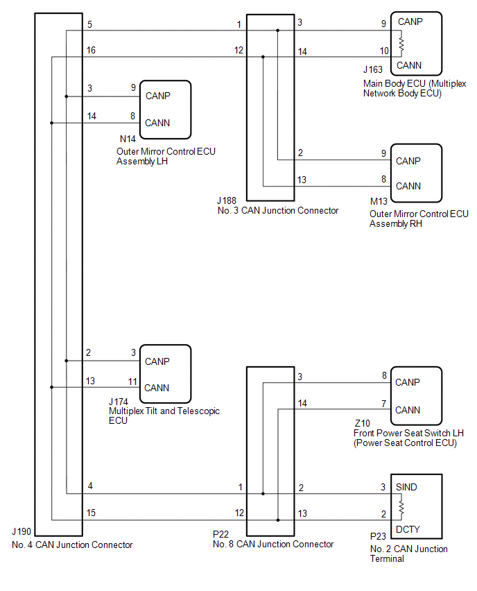
| Main body ECU (multiplex network body ECU) | WIRING DIAGRAM
 CAUTION / NOTICE / HINT
CAUTION: When performing the confirmation driving pattern, obey all speed limits and traffic laws.
NOTICE:
HINT:
- Before disconnecting related connectors for inspection, push in on each
connector body to check that the connector is not loose or disconnected.
- When a connector is disconnected, check that the terminals and connector body are not cracked, deformed or corroded.
PROCEDURE
(a) Disconnect the cable from the negative (-) battery terminal.
| (b) Measure the resistance according to the value(s) in the table below.
Standard Resistance: |
Tester Connection | Condition |
Specified Condition | Resistance: Malfunction | |
P23-3 (SIND) - P23-2 (DCTY) |
Cable disconnected from negative (-) battery terminal |
54 to 69 Ω | Below 53 Ω: Short in line | |
P23-3 (SIND) - P23-2 (DCTY) |
Cable disconnected from negative (-) battery terminal |
54 to 69 Ω | Higher than 70 Ω: Open in CAN main bus line | |
P23-3 (SIND) - J17-16 (BAT) |
Cable disconnected from negative (-) battery terminal |
6 kΩ or higher | Below 6 kΩ: +B short | |
P23-2 (DCTY) - J17-16 (BAT) |
Cable disconnected from negative (-) battery terminal |
6 kΩ or higher | Below 6 kΩ: +B short | |
P23-3 (SIND) - P23-1 (E) |
Cable disconnected from negative (-) battery terminal |
200 Ω or higher | Below 200 Ω: Ground short | |
P23-2 (DCTY) - P23-1 (E) |
Cable disconnected from negative (-) battery terminal |
200 Ω or higher | Below 200 Ω: Ground short | |
 |
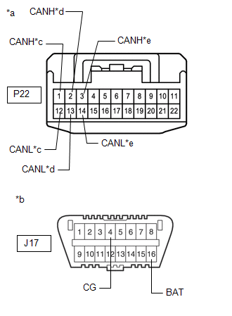
|
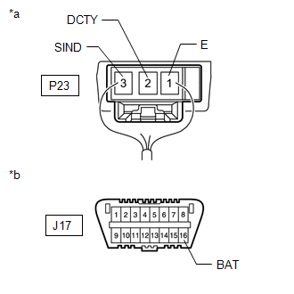
*a | Component with harness connected
(No. 2 CAN Junction Terminal) | |
*b | Front view of DLC3 | | |
|
Result | Proceed to | |
OK | A | |
NG - Open in CAN main wire |
B | | NG
- Short in CAN bus wire |
C | | NG
- +B short - Ground short |
D |
| B |
 | GO TO STEP 3 |
| C |
| GO TO STEP 12 |
| D |
| GO TO STEP 20 |
|
A |
 | |
(a) Reconnect the cable to the negative (-) battery terminal.
NOTICE: When disconnecting the cable, some systems need to be initialized after the cable is reconnected.
Click here  (b) Connect the Techstream to the DLC3.
(c) Turn the ignition switch to ON. (d) Turn the Techstream on.
(e) Enter the following menus: Body Electrical / (desired system) / Trouble Codes.
(f) Clear the DTCs. (g) Check for DTCs.
|
Result | Proceed to | |
DTC U1002 is output from main body ECU (multiplex network body ECU) |
A | | Other DTC is output |
B |
| A |
| REPLACE MAIN BODY ECU (MULTIPLEX NETWORK BODY ECU) |
| B |
| GO TO DIAGNOSTIC TROUBLE CODE CHART |
| 3. |
CHECK FOR OPEN IN CAN BUS MAIN WIRE (NO. 4 CAN JUNCTION CONNECTOR) |
| (a) Disconnect the No. 4 CAN junction connector. |
 |
|
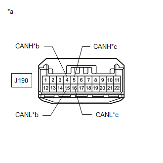
*a | Front view of wire harness connector
(to No. 4 CAN Junction Connector) | |
*b | to No. 8 CAN Junction Connector | |
*c | to No. 3 CAN Junction Connector | | |
(b) Measure the resistance according to the value(s) in the table below.
Standard Resistance: |
Tester Connection | Condition |
Specified Condition | Connected to | |
J190-4 (CANH) - J190-15 (CANL) |
Cable disconnected from negative (-) battery terminal |
108 to 132 Ω | No. 8 CAN junction connector | |
J190-5 (CANH) - J190-16 (CANL) |
Cable disconnected from negative (-) battery terminal |
108 to 132 Ω | No. 3 CAN junction connector |
|
Result | Proceed to | |
OK | A | |
NG (No. 3 CAN junction connector CAN main wire) |
B | | NG (No. 8 CAN junction connector CAN main wire) |
C |
| A |
| REPLACE NO. 4 CAN JUNCTION CONNECTOR |
| C |
| GO TO STEP 8 |
|
B | |
| |
(a) Reconnect the J190 No. 4 CAN junction connector.
|
NEXT | |
| |
| 5. |
CHECK FOR OPEN IN CAN BUS MAIN WIRE (NO. 3 CAN JUNCTION CONNECTOR) |
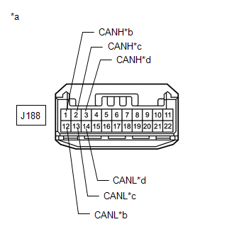
| (a) Disconnect the No. 3 CAN junction connector. |
 |
|
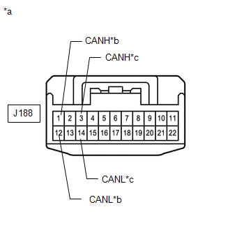
*a | Front view of wire harness connector
(to No. 3 CAN Junction Connector) | |
*b | to No. 4 CAN Junction Connector | |
*c | to Main Body ECU (Multiplex Network Body ECU) | | |
(b) Measure the resistance according to the value(s) in the table below.
Standard Resistance: |
Tester Connection | Condition |
Specified Condition | Connected to | |
J188-1 (CANH) - J188-12 (CANL) |
Cable disconnected from negative (-) battery terminal |
108 to 132 Ω | No. 4 CAN junction connector | |
J188-3 (CANH) - J188-14 (CANL) |
Cable disconnected from negative (-) battery terminal |
108 to 132 Ω | Main body ECU (multiplex network body ECU) |
|
Result | Proceed to | |
OK | A | |
NG (Main body ECU [multiplex network body ECU] CAN main wire) |
B | | NG (No. 4 CAN junction connector CAN main wire) |
C |
| A |
| REPLACE NO. 3 CAN JUNCTION CONNECTOR |
| C |
| REPAIR OR REPLACE CAN MAIN WIRE OR CONNECTOR (NO. 3 CAN JUNCTION CONNECTOR - NO. 4 CAN JUNCTION CONNECTOR) |
|
B | |
| |
(a) Reconnect the J188 No. 3 CAN junction connector.
|
NEXT | |
| |
| 7. |
CHECK FOR OPEN IN CAN BUS MAIN WIRE (MAIN BODY ECU [MULTIPLEX NETWORK BODY ECU]- NO. 3 CAN JUNCTION CONNECTOR) |
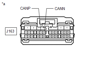
| (a) Disconnect the main body ECU (multiplex network body ECU) connector. |
 |
|
*a | Front view of wire harness connector
(to Main Body ECU [Multiplex Network Body ECU]) | | |
(b) Measure the resistance according to the value(s) in the table below.
Standard Resistance: |
Tester Connection | Condition |
Specified Condition | |
J163-9 (CANP) - J163-10 (CANN) |
Cable disconnected from negative (-) battery terminal |
108 to 132 Ω |
| OK |
| REPLACE MAIN BODY ECU (MULTIPLEX NETWORK BODY ECU) |
| NG |
| REPAIR
OR REPLACE CAN MAIN WIRE OR CONNECTED TO MAIN BODY ECU (MAIN BODY ECU
[MULTIPLEX NETWORK BODY ECU] - NO. 3 CAN JUNCTION CONNECTOR) |
(a) Reconnect the J190 No. 4 CAN junction connector.
|
NEXT | |
| |
| 9. |
CHECK FOR OPEN IN CAN BUS MAIN WIRE (NO. 8 CAN JUNCTION CONNECTOR) |
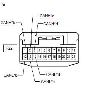
| (a) Disconnect the No. 8 CAN junction connector. |
 |
|
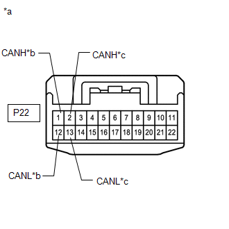
*a | Front view of wire harness connector
(to No. 8 CAN Junction Connector) | |
*b | to No. 4 CAN Junction Connector | |
*c | to No. 2 CAN Junction Terminal | | |
(b) Measure the resistance according to the value(s) in the table below.
Standard Resistance: |
Tester Connection | Condition |
Specified Condition | Connected to | |
P22-1 (CANH) - P22-12 (CANL) |
Cable disconnected from negative (-) battery terminal |
108 to 132 Ω | No. 4 CAN junction connector | |
P22-2 (CANH) - P22-13 (CANL) |
Cable disconnected from negative (-) battery terminal |
108 to 132 Ω | No. 2 CAN junction terminal |
|
Result | Proceed to | |
OK | A | |
NG (to No. 2 CAN junction terminal CAN main wire) |
B | | NG (to No. 4 CAN junction connector CAN main wire) |
C |
| A |
| REPLACE NO. 8 CAN JUNCTION CONNECTOR |
| C |
| REPAIR OR REPLACE CAN MAIN WIRE OR CONNECTOR (NO. 8 CAN JUNCTION CONNECTOR - NO. 4 CAN JUNCTION CONNECTOR) |
|
B | |
| |
(a) Reconnect the P22 No. 8 CAN junction connector.
|
NEXT | |
| |
| 11. |
CHECK FOR OPEN IN CAN BUS MAIN WIRE (NO. 2 CAN JUNCTION TERMINAL - NO. 8 CAN JUNCTION CONNECTOR) |
| (a) Disconnect the No. 2 CAN junction terminal connector. |
 |
|
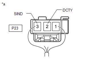
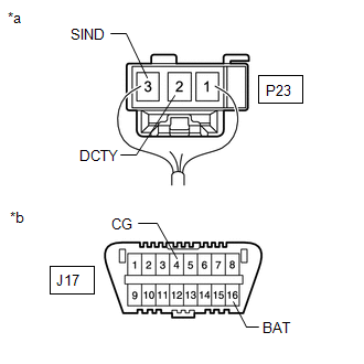
*a | Rear view of wire harness connector
(to No. 2 CAN Junction Terminal) | | |
(b) Measure the resistance according to the value(s) in the table below.
Standard Resistance: |
Tester Connection | Condition |
Specified Condition | |
P23-3 (SIND) - P23-2 (DCTY) |
Cable disconnected from negative (-) battery terminal |
108 to 132 Ω |
| OK |
| REPLACE NO. 2 CAN JUNCTION TERMINAL |
| NG |
| REPAIR OR REPLACE CAN MAIN WIRE OR CONNECTOR (NO. 2 CAN JUNCTION TERMINAL - NO. 8 CAN JUNCTION CONNECTOR) |
| 12. |
CHECK FOR SHORT IN CAN BUS WIRES (NO. 4 CAN JUNCTION CONNECTOR) |
| (a) Disconnect the No. 4 CAN junction connector. |
 |
|
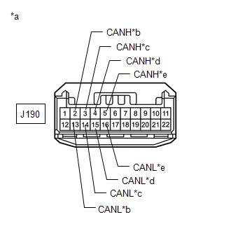
*a | Front view of wire harness connector
(to No. 4 CAN Junction Connector) | |
*b | to Multiplex Tilt and Telescopic ECU | |
*c | to Outer Mirror Control ECU Assembly LH | |
*d | to No. 8 CAN Junction Connector | |
*e | to No. 3 CAN Junction Connector | | |
(b) Measure the resistance according to the value(s) in the table below.
Standard Resistance: |
Tester Connection | Condition |
Specified Condition | Connected to | |
J190-2 (CANH) - J190-13 (CANL) |
Cable disconnected from negative (-) battery terminal |
200 Ω or higher | Multiplex tilt and telescopic ECU | |
J190-3 (CANH) - J190-14 (CANL) |
Cable disconnected from negative (-) battery terminal |
200 Ω or higher | Outer mirror control ECU assembly LH | |
J190-4 (CANH) - J190-15 (CANL) |
Cable disconnected from negative (-) battery terminal |
108 to 132 Ω | No. 8 CAN junction connector | |
J190-5 (CANH) - J190-16 (CANL) |
Cable disconnected from negative (-) battery terminal |
108 to 132 Ω | No. 3 CAN junction connector |
|
Result | Proceed to | |
OK | A | |
NG (No. 3 CAN junction connector CAN main wire) |
B | | NG (No. 8 CAN junction connector CAN main wire) |
C | | NG (ECU or sensor CAN branch wire) |
D |
| A |
| REPLACE NO. 4 CAN JUNCTION CONNECTOR |
| C |
| GO TO STEP 16 |
| D |
| GO TO STEP 25 |
|
B | |
| |
(a) Reconnect the J190 No. 4 CAN junction connector.
|
NEXT | |
| |
| 14. |
CHECK FOR SHORT IN CAN BUS WIRES (NO. 3 CAN JUNCTION CONNECTOR) |
| (a) Disconnect the No. 3 CAN junction connector. |
 |
|
*a | Front view of wire harness connector
(to No. 3 CAN Junction Connector) | |
*b | to No. 4 CAN Junction Connector | |
*c | to Outer Mirror Control ECU Assembly RH | |
*d | to Main Body ECU (Multiplex Network Body ECU) | | |
(b) Measure the resistance according to the value(s) in the table below.
Standard Resistance: |
Tester Connection | Condition |
Specified Condition | Connected to | |
J188-1 (CANH) - J188-12 (CANL) |
Cable disconnected from negative (-) battery terminal |
108 to 132 Ω | No. 4 CAN junction connector | |
J188-2 (CANH) - J188-13 (CANL) |
Cable disconnected from negative (-) battery terminal |
200 Ω or higher | Outer mirror control ECU assembly RH | |
J188-3 (CANH) - J188-14 (CANL) |
Cable disconnected from negative (-) battery terminal |
108 to 132 Ω | Main body ECU (multiplex network body ECU) |
|
Result | Proceed to | |
OK | A | |
NG (Main body ECU [multiplex network body ECU] CAN main wire) |
B | | NG (No. 4 CAN junction connector CAN main wire) |
C | | NG (ECU or sensor CAN branch wire) |
D |
| A |
| REPLACE NO. 3 CAN JUNCTION CONNECTOR |
| C |
| REPAIR OR REPLACE CAN MAIN WIRE OR CONNECTOR (NO. 3 CAN JUNCTION CONNECTOR - NO. 4 CAN JUNCTION CONNECTOR) |
| D |
| GO TO STEP 25 |
|
B | |
| |
| 15. |
CHECK SHORT IN CAN BUS WIRES (MAIN BODY ECU [MULTIPLEX NETWORK BODY ECU]- NO. 3 CAN JUNCTION CONNECTOR) |
| (a) Disconnect the main body ECU (multiplex network body ECU) connector. |
|
|
|
*a | Front view of wire harness connector
(to Main Body ECU [Multiplex Network Body ECU]) | | |
(b) Measure the resistance according to the value(s) in the table below.
Standard Resistance: |
Tester Connection | Condition |
Specified Condition | |
J163-9 (CANP) - J163-10 (CANN) |
Cable disconnected from negative (-) battery terminal |
108 to 132 Ω |
| OK |
| REPLACE MAIN BODY ECU (MULTIPLEX NETWORK BODY ECU) |
| NG |
| REPAIR
OR REPLACE CAN MAIN WIRE OR CONNECTED TO MAIN BODY ECU (MAIN BODY ECU
[MULTIPLEX NETWORK BODY ECU] - NO. 3 CAN JUNCTION CONNECTOR) |
(a) Reconnect the J190 No. 4 CAN junction connector.
|
NEXT | |
| |
| 17. |
CHECK FOR SHORT IN CAN BUS WIRES (NO. 8 CAN JUNCTION CONNECTOR) |
| (a) Disconnect the No. 8 CAN junction connector. |
 |
|
*a | Front view of wire harness connector
(to No. 8 CAN Junction Connector) | |
*b | to No. 4 CAN Junction Connector | |
*c | to No. 2 CAN Junction Terminal | |
*d | to Front Power Seat Switch LH (Power Seat Control ECU) | | |
(b) Measure the resistance according to the value(s) in the table below.
Standard Resistance: |
Tester Connection | Condition |
Specified Condition | Connected to | |
P22-1 (CANH) - P22-12 (CANL) |
Cable disconnected from negative (-) battery terminal |
108 to 132 Ω | No. 4 CAN junction connector | |
P22-2 (CANH) - P22-13 (CANL) |
Cable disconnected from negative (-) battery terminal |
108 to 132 Ω | No. 2 CAN junction terminal | |
P22-3 (CANH) - P22-14 (CANL) |
Cable disconnected from negative (-) battery terminal |
200 Ω or higher | Front power seat switch LH (power seat control ECU) |
|
Result | Proceed to | |
OK | A | |
NG (No. 2 CAN junction terminal CAN main wire) |
B | | NG (No. 4 CAN junction connector CAN main wire) |
C | | NG (Wire to ECU or sensor) |
D |
| A |
| REPLACE NO. 8 CAN JUNCTION CONNECTOR |
| C |
| REPAIR OR REPLACE CAN MAIN WIRE OR CONNECTOR (NO. 8 CAN JUNCTION CONNECTOR - NO. 4 CAN JUNCTION CONNECTOR) |
| D |
| GO TO STEP 25 |
|
B | |
| |
(a) Reconnect the P22 No. 8 CAN junction connector.
|
NEXT | |
| |
| 19. |
CHECK SHORT IN CAN BUS WIRES (NO. 2 CAN JUNCTION TERMINAL - NO. 8 CAN JUNCTION CONNECTOR) |
| (a) Disconnect the No. 2 CAN junction terminal connector. |
|
|
|
*a | Rear view of wire harness connector
(to No. 2 CAN Junction Terminal) | | |
(b) Measure the resistance according to the value(s) in the table below.
Standard Resistance: |
Tester Connection | Condition |
Specified Condition | |
P23-3 (SIND) - P23-2 (DCTY) |
Cable disconnected from negative (-) battery terminal |
108 to 132 Ω |
| OK |
| REPLACE NO. 2 CAN JUNCTION TERMINAL |
| NG |
| REPAIR OR REPLACE CAN MAIN WIRE OR CONNECTOR (NO. 2 CAN JUNCTION TERMINAL - NO. 8 CAN JUNCTION CONNECTOR) |
| 20. |
CHECK FOR SHORT IN CAN BUS WIRES (NO. 4 CAN JUNCTION CONNECTOR) |
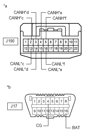
| (a) Disconnect the No. 4 CAN junction connector. |
 |
|
*a | Front view of wire harness connector
(to No. 4 CAN Junction Connector) | |
*b | Front view of DLC3 | |
*c | to Multiplex Tilt and Telescopic ECU | |
*d | to Outer Mirror Control ECU Assembly LH | |
*e | to No. 8 CAN Junction Connector | |
*f | to No. 3 CAN Junction Connector | | |
(b) Measure the resistance according to the value(s) in the table below.
Standard Resistance: |
Tester Connection | Condition |
Specified Condition | Connected to | |
J190-2 (CANH) - J17-4 (CG) |
Cable disconnected from negative (-) battery terminal |
200 Ω or higher |
Multiplex tilt and telescopic ECU | |
J190-13 (CANL) - J17-4 (CG) | |
J190-2 (CANH) - J17-16 (BAT) |
Cable disconnected from negative (-) battery terminal |
6 kΩ or higher | |
J190-13 (CANL) - J17-16 (BAT) | |
J190-3 (CANH) - J17-4 (CG) |
Cable disconnected from negative (-) battery terminal |
200 Ω or higher |
Outer mirror control ECU assembly LH | |
J190-14 (CANL) - J17-4 (CG) | |
J190-3 (CANH) - J17-16 (BAT) |
Cable disconnected from negative (-) battery terminal |
6 kΩ or higher | |
J190-14 (CANL) - J17-16 (BAT) | |
J190-4 (CANH) - J17-4 (CG) |
Cable disconnected from negative (-) battery terminal |
200 Ω or higher |
No. 8 CAN junction connector | |
J190-15 (CANL) - J17-4 (CG) | |
J190-4 (CANH) - J17-16 (BAT) |
Cable disconnected from negative (-) battery terminal |
6 kΩ or higher | |
J190-15 (CANL) - J17-16 (BAT) | |
J190-5 (CANH) - J17-4 (CG) |
Cable disconnected from negative (-) battery terminal |
200 Ω or higher |
No. 3 CAN junction connector | |
J190-16 (CANL) - J17-4 (CG) | |
J190-5 (CANH) - J17-16 (BAT) |
Cable disconnected from negative (-) battery terminal |
6 kΩ or higher | |
J190-16 (CANL) - J17-16 (BAT) |
|
Result | Proceed to | |
OK | A | |
NG (No. 3 CAN junction connector CAN main wire) |
B | | NG (No. 8 CAN junction connector CAN main wire) |
C | | NG (Wire to ECU or sensor) |
D |
| A |
| REPLACE NO. 4 CAN JUNCTION CONNECTOR |
| C |
| GO TO STEP 23 |
| D |
| GO TO STEP 25 |
|
B | |
| |
(a) Reconnect the J190 No. 4 CAN junction connector.
|
NEXT | |
| |
| 22. |
CHECK FOR SHORT IN CAN BUS WIRES (NO. 3 CAN JUNCTION CONNECTOR) |
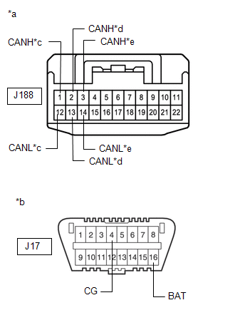
| (a) Disconnect the No. 3 CAN junction connector. |
 |
|
*a | Front view of wire harness connector
(to No. 3 CAN Junction Connector) | |
*b | Front view of DLC3 | |
*c | to No. 4 CAN Junction Connector | |
*d | to Outer Mirror Control ECU Assembly RH | |
*e | to Main Body ECU (Multiplex Network Body ECU) | | |
(b) Measure the resistance according to the value(s) in the table below.
Standard Resistance: |
Tester Connection | Condition |
Specified Condition | Connected to | |
J188-1 (CANH) - J17-4 (CG) |
Cable disconnected from negative (-) battery terminal |
200 Ω or higher |
No. 4 CAN junction connector | |
J188-12 (CANL) - J17-4 (CG) | |
J188-1 (CANH) - J17-16 (BAT) |
Cable disconnected from negative (-) battery terminal |
6 kΩ or higher | |
J188-12 (CANL) - J17-16 (BAT) | |
J188-2 (CANH) - J17-4 (CG) |
Cable disconnected from negative (-) battery terminal |
200 Ω or higher |
Outer mirror control ECU assembly RH | |
J188-13 (CANL) - J17-4 (CG) | |
J188-2 (CANH) - J17-16 (BAT) |
Cable disconnected from negative (-) battery terminal |
6 kΩ or higher | |
J188-13 (CANL) - J17-16 (BAT) | |
J188-3 (CANH) - J17-4 (CG) |
Cable disconnected from negative (-) battery terminal |
200 Ω or higher |
Main body ECU (multiplex network body ECU) | |
J188-14 (CANL) - J17-4 (CG) | |
J188-3 (CANH) - J17-16 (BAT) |
Cable disconnected from negative (-) battery terminal |
6 kΩ or higher | |
J188-14 (CANL) - J17-16 (BAT) |
|
Result | Proceed to | |
OK | A | |
NG (No. 4 CAN junction connector CAN main wire) |
B | | NG (Wire to ECU or sensor) |
C |
| A |
| REPLACE NO. 3 CAN JUNCTION CONNECTOR |
| B |
| REPAIR OR REPLACE CAN MAIN WIRE OR CONNECTOR (NO. 3 CAN JUNCTION CONNECTOR - NO. 4 CAN JUNCTION CONNECTOR) |
| C |
| GO TO STEP 25 |
(a) Reconnect the J190 No. 4 CAN junction connector.
|
NEXT | |
| |
| 24. |
CHECK FOR SHORT IN CAN BUS WIRES (NO. 8 CAN JUNCTION CONNECTOR) |
| (a) Disconnect the No. 8 CAN junction connector. |
 |
|
*a | Front view of wire harness connector
(to No. 8 CAN Junction Connector) | |
*b | Front view of DLC3 | |
*c | to No. 4 CAN Junction Connector | |
*d | to No. 2 CAN Junction Terminal | |
*e | to Front Power Seat Switch LH (Power Seat Control ECU) | | |
(b) Measure the resistance according to the value(s) in the table below.
Standard Resistance: |
Tester Connection | Condition |
Specified Condition | Connected to | |
P22-1 (CANH) - J17-4 (CG) |
Cable disconnected from negative (-) battery terminal |
200 Ω or higher |
No. 4 CAN junction connector | |
P22-12 (CANL) - J17-4 (CG) | |
P22-1 (CANH) - J17-16 (BAT) |
Cable disconnected from negative (-) battery terminal |
6 kΩ or higher | |
P22-12 (CANL) - J17-16 (BAT) | |
P22-2 (CANH) - J17-4 (CG) |
Cable disconnected from negative (-) battery terminal |
200 Ω or higher |
No. 2 CAN junction terminal | |
P22-13 (CANL) - J17-4 (CG) | |
P22-2 (CANH) - J17-16 (BAT) |
Cable disconnected from negative (-) battery terminal |
6 kΩ or higher | |
P22-13 (CANL) - J17-16 (BAT) | |
P22-3 (CANH) - J17-4 (CG) |
Cable disconnected from negative (-) battery terminal |
200 Ω or higher |
Front power seat switch LH (power seat control ECU) | |
P22-14 (CANL) - J17-4 (CG) | |
P22-3 (CANH) - J17-16 (BAT) |
Cable disconnected from negative (-) battery terminal |
6 kΩ or higher | |
P22-14 (CANL) - J17-16 (BAT) |
|
Result | Proceed to | |
OK | A | |
NG (No. 4 CAN junction connector CAN main wire) |
B | | NG (Wire to ECU or sensor) |
C |
| A |
| REPLACE NO. 8 CAN JUNCTION CONNECTOR |
| B |
| REPAIR OR REPLACE CAN MAIN WIRE OR CONNECTOR (NO. 8 CAN JUNCTION CONNECTOR - NO. 4 CAN JUNCTION CONNECTOR) |
| C |
| GO TO STEP 25 |
| 25. |
CHECK FOR SHORT IN CAN BUS WIRES (ECU, SENSOR) |
(a) Reconnect all wire harness connectors.
| (b)
Disconnect the connector that includes terminals CANH and CANL from the
ECU or sensor to which the short circuited main/branch line is
connected. Click here |
 |
|
*a | Component with harness connected
(No. 2 CAN Junction Terminal) | |
*b | Front view of DLC3 | | |
(c) Measure the resistance according to the value(s) in the table below.
Standard Resistance: |
Tester Connection | Condition |
Specified Condition | |
P23-3 (SIND) - P23-2 (DCTY) |
Cable disconnected from negative (-) battery terminal |
54 to 69 Ω | |
P23-3 (SIND) - J17-4 (CG) |
Cable disconnected from negative (-) battery terminal |
200 Ω or higher | |
P23-2 (DCTY) - J17-4 (CG) |
Cable disconnected from negative (-) battery terminal |
200 Ω or higher | |
P23-3 (SIND) - J17-16 (BAT) |
Cable disconnected from negative (-) battery terminal |
6 kΩ or higher | |
P23-2 (DCTY) - J17-16 (BAT) |
Cable disconnected from negative (-) battery terminal |
6 kΩ or higher |
HINT:
- If the resistance becomes normal (between 54 and 69 Ω) when the
connector is disconnected from the ECU or sensor, there may be a short
to CAN bus lines in the ECU or sensor.
- If the resistance changes to 6 kΩ or higher when the connector is
disconnected from the ECU or sensor, there may be a short to B+ in the
ECU or sensor.
- If the resistance changes to 200 Ω or higher when the connector is
disconnected from the ECU or sensor, there may be a short to GND in the
ECU or sensor.
- If the resistance does not become normal when the connector is
disconnected from the ECU or sensor, check for a short circuit in the
wire harness and repair or replace the wire harness or connector if
necessary.
| OK |
| REPLACE ECU OR SENSOR |
| NG |
| REPAIR OR REPLACE HARNESS OR CONNECTOR | | 

