COMPONENTS ILLUSTRATION 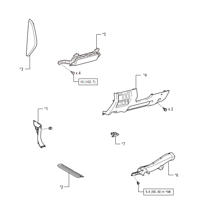
ILLUSTRATION 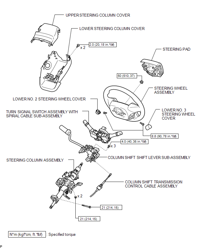 ILLUSTRATION 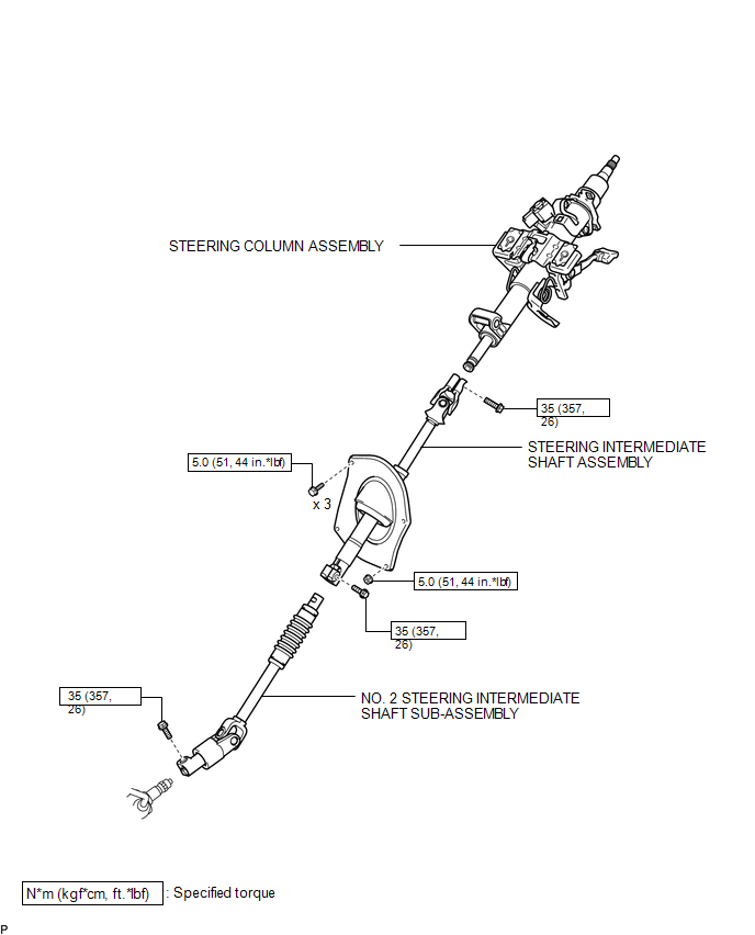 ILLUSTRATION 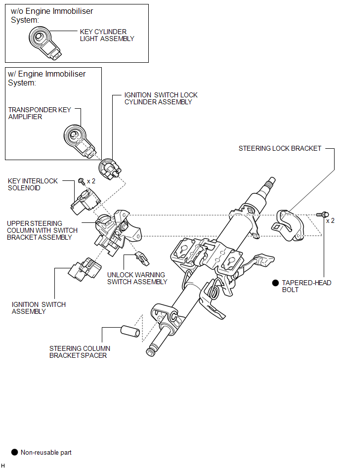 |
Toyota Tundra Service Manual > Vehicle Stability Control System: Stop Light Control Relay Malfunction (C1380)
DESCRIPTION When the skid control ECU (brake actuator assembly) applies the brakes after receiving a brake request signal from the trailer sway control, the skid control ECU (brake actuator assembly) operates the stop light switch assembly to illuminate the stop lights. DTC No. Detection Item DTC De ...


