INSTALLATION PROCEDURE 1. INSTALL STEERING COLUMN ASSEMBLY
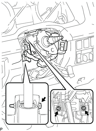
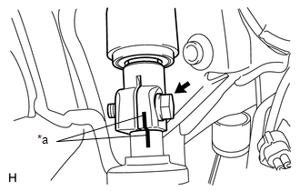
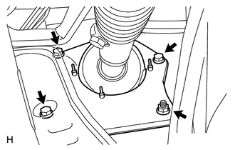
2. INSTALL NO. 2 STEERING INTERMEDIATE SHAFT SUB-ASSEMBLY
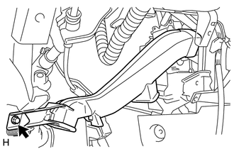
(b) Install the bolt. Torque: 35 N·m {357 kgf·cm, 26 ft·lbf} 3. INSTALL STEERING INTERMEDIATE SHAFT ASSEMBLY
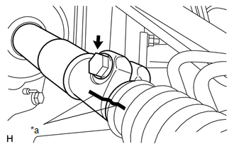
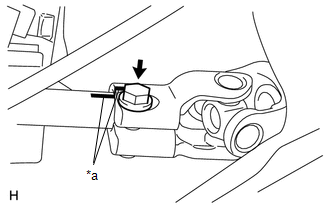
(b) Install the bolt. Torque: 35 N·m {357 kgf·cm, 26 ft·lbf}
(d) Install the bolt. Torque: 35 N·m {357 kgf·cm, 26 ft·lbf}
4. INSTALL NO. 3 AIR DUCT SUB-ASSEMBLY
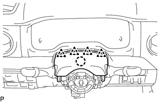
5. INSTALL LOWER NO. 1 INSTRUMENT PANEL AIRBAG ASSEMBLY
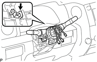
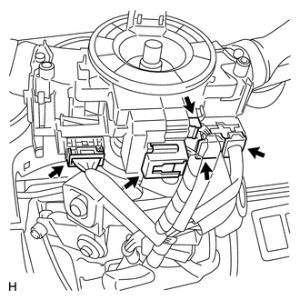
6. INSTALL LOWER INSTRUMENT PANEL FINISH PANEL SUB-ASSEMBLY LH 7. INSTALL INSTRUMENT SIDE PANEL LH 8. INSTALL COWL SIDE TRIM BOARD LH 9. INSTALL FRONT DOOR SCUFF PLATE LH 10. INSTALL COLUMN SHIFT SHIFT LEVER SUB-ASSEMBLY 11. CONNECT COLUMN SHIFT TRANSMISSION CONTROL CABLE ASSEMBLY 12. INSTALL TURN SIGNAL SWITCH ASSEMBLY WITH SPIRAL CABLE SUB-ASSEMBLY
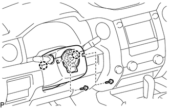
13. INSTALL UPPER STEERING COLUMN COVER
(b) Attach the 4 clips. 14. INSTALL LOWER STEERING COLUMN COVER
(b) Install the 2 screws. Torque: 2.0 N·m {20 kgf·cm, 18 in·lbf} 15. ADJUST SPIRAL CABLE 16. INSTALL STEERING WHEEL ASSEMBLY
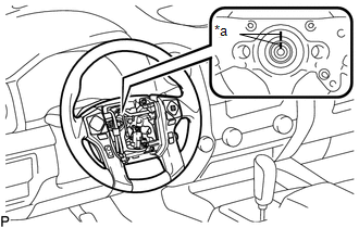
(b) Install the steering wheel set nut. Torque: 50 N·m {510 kgf·cm, 37 ft·lbf} 17. INSPECT STEERING WHEEL CENTER POINT 18. INSTALL STEERING PAD 19. INSTALL LOWER NO. 3 STEERING WHEEL COVER 20. INSTALL LOWER NO. 2 STEERING WHEEL COVER 21. CONNECT CABLE TO NEGATIVE BATTERY TERMINAL Torque: 5.4 N·m {55 kgf·cm, 48 in·lbf} NOTICE: Some systems need to be initialized after the cable is reconnected (See page
22. CHECK SRS WARNING LIGHT (See page
|
Toyota Tundra Service Manual > Front Bumper: Removal
REMOVAL PROCEDURE 1. REMOVE RADIATOR GRILLE SUB-ASSEMBLY Click here 2. REMOVE FRONT END PANEL LH (a) Put protective tape around the front end panel LH. Text in Illustration *1 Protective Tape (b) Remove the 2 screws and 2 clips. (c) Detach the 3 claws and remove the front end panel LH. 3. REMOVE FRO ...