REASSEMBLY PROCEDURE 1. INSTALL STEERING COLUMN BRACKET SPACER
2. INSTALL IGNITION SWITCH ASSEMBLY
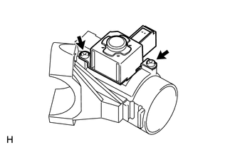
3. INSTALL KEY INTERLOCK SOLENOID
4. INSTALL UNLOCK WARNING SWITCH ASSEMBLY
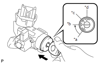
5. INSTALL IGNITION SWITCH LOCK CYLINDER (a) Check that the ignition switch lock cylinder is in the ACC position.
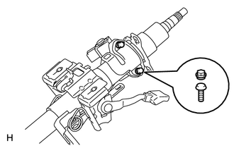
(c) Check that the ignition switch lock cylinder is securely installed. 6. INSPECT STEERING LOCK OPERATION 7. INSTALL UPPER STEERING COLUMN CLAMP WITH SWITCH BRACKET ASSEMBLY (a) Temporarily install the upper steering column with switch bracket and the steering lock bracket with 2 new tapered-head bolts.
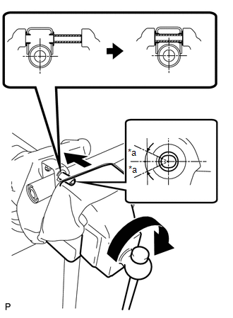
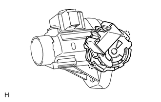
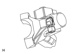
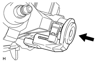
8. INSTALL TRANSPONDER KEY AMPLIFIER (w/ Engine Immobiliser System) (a) Align the transponder key amplifier with the installation position of the upper bracket with the amplifier inclined.
9. INSTALL KEY CYLINDER LIGHT ASSEMBLY (w/o Engine Immobiliser System) (a) Align the key cylinder light with the installation position of the switch bracket with the key cylinder light inclined.
|
Toyota Tundra Service Manual > Front Passenger Airbag Assembly: Installation
INSTALLATION PROCEDURE 1. INSTALL FRONT PASSENGER AIRBAG ASSEMBLY (a) Attach the 5 hooks (A). (b) Attach the 5 hooks (B) and install the front passenger airbag on the instrument panel. (c) Install the 2 screws. 2. INSTALL NO. 3 INSTRUMENT PANEL WIRE (a) Attach the wire harness clamp to install the N ...