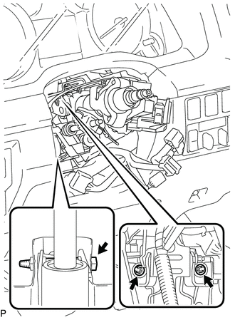
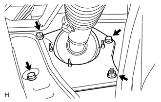
INSTALLATION PROCEDURE 1. INSTALL STEERING COLUMN ASSEMBLY
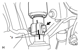
2. INSTALL NO. 2 STEERING INTERMEDIATE SHAFT SUB-ASSEMBLY
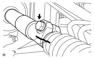
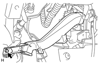
(b) Install the bolt. Torque: 35 N·m {357 kgf·cm, 26 ft·lbf} 3. INSTALL STEERING INTERMEDIATE SHAFT ASSEMBLY
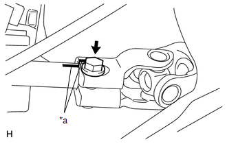
(b) Install the bolt. Torque: 35 N·m {357 kgf·cm, 26 ft·lbf}
(d) Install the bolt. Torque: 35 N·m {357 kgf·cm, 26 ft·lbf}
4. INSTALL NO. 3 AIR DUCT SUB-ASSEMBLY
5. INSTALL LOWER NO. 1 INSTRUMENT PANEL AIRBAG ASSEMBLY
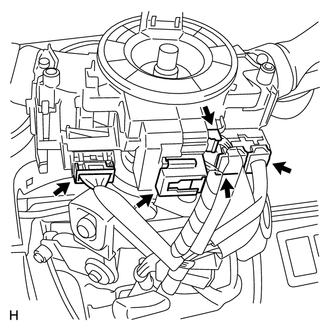
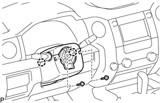
6. INSTALL LOWER INSTRUMENT PANEL FINISH PANEL SUB-ASSEMBLY LH 7. INSTALL INSTRUMENT SIDE PANEL LH 8. INSTALL COWL SIDE TRIM BOARD LH 9. INSTALL FRONT DOOR SCUFF PLATE LH 10. INSTALL TURN SIGNAL SWITCH ASSEMBLY WITH SPIRAL CABLE SUB-ASSEMBLY
11. INSTALL UPPER STEERING COLUMN COVER
(b) Attach the 4 clips. 12. INSTALL LOWER STEERING COLUMN COVER
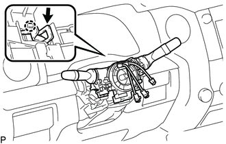
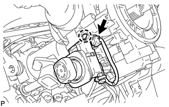
(b) Install the 2 screws. 13. INSTALL TILT AND TELESCOPIC MANUAL SWITCH
(b) Connect the connector. 14. ADJUST SPIRAL CABLE
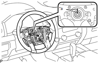
15. INSTALL STEERING WHEEL ASSEMBLY
(b) Install the steering wheel set nut. Torque: 50 N·m {510 kgf·cm, 37 ft·lbf} 16. INSPECT STEERING WHEEL CENTER POINT 17. ADJUST SPIRAL CABLE 18. INSTALL STEERING PAD
19. INSTALL LOWER NO. 3 STEERING WHEEL COVER 20. INSTALL LOWER NO. 2 STEERING WHEEL COVER 21. CONNECT CABLE TO NEGATIVE BATTERY TERMINAL Torque: 5.4 N·m {55 kgf·cm, 48 in·lbf} NOTICE: Some systems need to be initialized after the cable is reconnected (See page
22. CHECK SRS WARNING LIGHT (See page
|
Toyota Tundra Service Manual > Power Tilt And Power Telescopic Steering Column System: Tilt and Telescopic Manual Switch Circuit Malfunction (B2603)
DESCRIPTION Different voltage values are sent to the multiplex tilt and telescopic ECU by operating the tilt and telescopic switch (headlight dimmer switch assembly). The multiplex tilt and telescopic ECU then judges which motor and in which direction that motor should operate based on the voltage v ...