DESCRIPTION
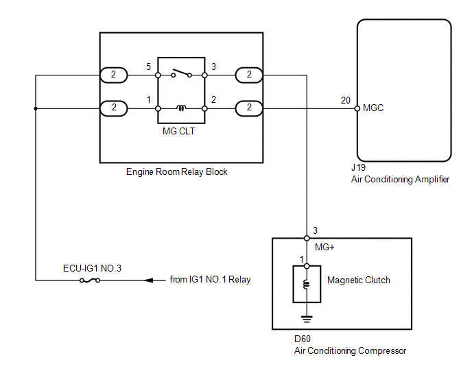
When the air conditioning amplifier is turned on, a magnetic clutch ON signal
is sent from the MGC terminal of the air conditioning amplifier. Then, the magnetic
clutch relay (MG CLT) turns on to operate the magnetic clutch.
WIRING DIAGRAM
PROCEDURE
|
1.
|
READ VALUE USING TECHSTREAM (A/C SIGNAL)
|
(a) Use the Data List to check if the air conditioning signal is functioning
properly.
Engine and ECT
|
Tester Display
|
Measurement Item / Range
|
Normal Condition
|
Diagnostic Note
|
|
A/C Signal
|
Air conditioning switch signal /
ON or OFF
|
ON: Air conditioning ON
OFF: Air conditioning OFF
|
-
|
OK:
The display is as specified in the normal condition.
| OK |
 |
PROCEED TO NEXT CIRCUIT INSPECTION SHOWN IN PROBLEM SYMPTOMS TABLE
|
| NG |

|
|
|
2.
|
INSPECT FUSE (ECU-IG1 NO.3)
|
(a) Remove the ECU-IG1 NO.3 fuse from the driver side junction block.
(b) Measure the resistance according to the value(s) in the table below.
Standard resistance:
|
Tester Connection
|
Condition
|
Specified Condition
|
|
ECU-IG1 NO.3 fuse
|
Always
|
Below 1 Ω
|
| NG |
|
REPLACE FUSE
|
| OK |
|
|
|
|
3.
|
CHECK HARNESS AND CONNECTOR (ENGINE ROOM RELAY BLOCK, JUNCTION BLOCK
- BATTERY)
|
(a) Remove the magnetic clutch relay (MG CLT) from the engine room relay block,
junction block.
(b) Measure the voltage according to the value(s) in the table below.
Standard voltage:
|
Tester Connection
|
Switch Condition
|
Specified Condition
|
|
Engine room relay block magnetic clutch relay terminal 5 - Body ground
|
Ignition switch ON
|
11 to 14 V
|
|
Ignition switch off
|
Below 1 V
|
|
Engine room relay block magnetic clutch relay terminal 1 - Body ground
|
Ignition switch ON
|
11 to 14 V
|
|
Ignition switch off
|
Below 1 V
|
| NG |
|
REPAIR OR REPLACE HARNESS OR CONNECTOR
|
| OK |
|
|
|
|
4.
|
INSPECT MAGNETIC CLUTCH RELAY (MG CLT)
|
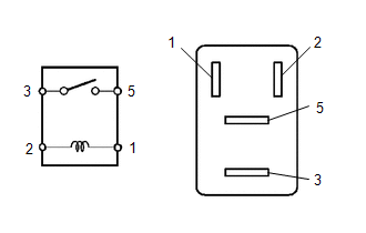
(a) Remove the magnetic clutch relay from the engine room relay block, junction
block.
(b) Measure the resistance according to the value(s) in the table below.
Standard resistance:
|
Tester Connection
|
Condition
|
Specified Condition
|
|
3 - 5
|
When battery voltage is not applied between terminals 1 and 2
|
10 kΩ or higher
|
|
When battery voltage is applied to terminals 1 and 2
|
Below 1 Ω
|
| NG |
|
REPLACE MAGNETIC CLUTCH RELAY
|
| OK |
|
|
|
|
5.
|
CHECK HARNESS AND CONNECTOR (AIR CONDITIONING AMPLIFIER - BATTERY)
|
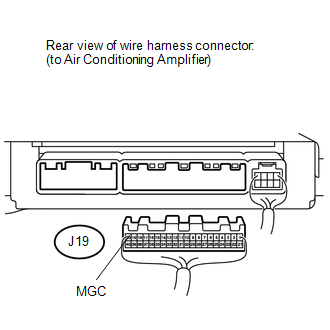
(a) Disconnect the J19 air conditioning amplifier connector.
(b) Measure the voltage according to the value(s) in the table below.
Standard voltage:
|
Tester Connection
|
Switch Condition
|
Specified Condition
|
|
J19-20 (MGC) - Body ground
|
Ignition switch OFF
|
Below 1 V
|
|
Ignition switch ON
|
11 to 14 V
|
| NG |
|
REPAIR OR REPLACE HARNESS OR CONNECTOR
|
| OK |
|
|
|
|
6.
|
CHECK AIR CONDITIONING AMPLIFIER (MGC VOLTAGE)
|
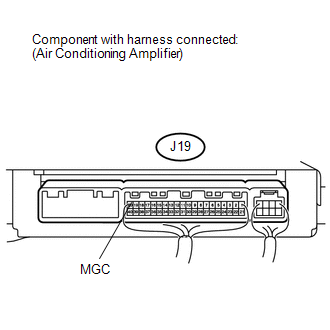
(a) Reconnect the J19 air conditioning amplifier connector.
(b) Measure the voltage according to the value(s) in the table below.
Standard voltage:
|
Tester Connection
|
Switch Condition
|
Specified Condition
|
|
J19-20 (MGC) - Body ground
|
Engine is running
Blower switch LO
A/C switch ON
|
Below 1 V
|
|
Engine is running
Blower switch LO
A/C switch OFF
|
11 to 14 V
|
| NG |
|
REPLACE AIR CONDITIONING AMPLIFIER
|
| OK |
|
|
|
|
7.
|
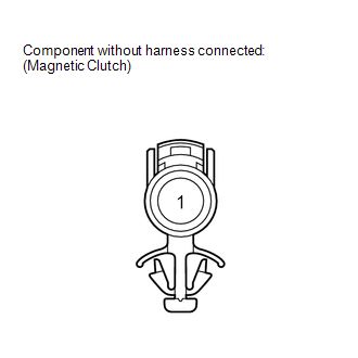
INSPECT AIR CONDITIONING COMPRESSOR (COMPRESSOR HARNESS)
|
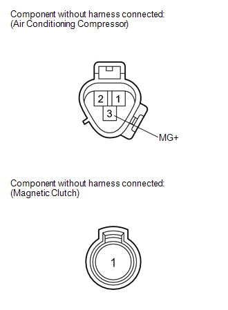
(a) Disconnect the D60 air conditioning compressor connector.
(b) Disconnect the magnetic clutch connector.
(c) Measure the resistance according to the value(s) in the table below.
Standard resistance:
|
Tester Connection
|
Condition
|
Specified Condition
|
|
3 (MG+) - 1
|
Always
|
Below 1 Ω
|
|
3 (MG+) or 1 - Body ground
|
Always
|
10 kΩ or higher
|
| NG |
|
REPAIR AIR CONDITIONING COMPRESSOR
|
| OK |
|
|
|
|
8.
|
INSPECT MAGNETIC CLUTCH
|
|
(a) Measure the resistance according to the value(s) in the table below.
Standard resistance:
|
Tester Connection
|
Condition
|
Specified Condition
|
|
1 - Body ground
|
Always
|
3.4 to 3.8 Ω
|
|
|
(b) When connector terminal 1 is connected to the positive (+) battery terminal,
check that the following occurs: 1) the magnetic clutch's operating sound can be
heard, and 2) the magnetic clutch's hub and rotor lock.
| NG |
|
REPLACE MAGNETIC CLUTCH
|
| OK |
|
|
|
|
9.
|
CHECK HARNESS AND CONNECTOR (AIR CONDITIONING COMPRESSOR - ENGINE ROOM
RELAY BLOCK, JUNCTION BLOCK)
|
(a) Disconnect the D60 air conditioning compressor connector.
(b) Remove the magnetic clutch relay (MG CLT) from the engine room relay block,
junction block.
(c) Measure the resistance according to the value(s) in the table below.
Standard resistance:
|
Tester Connection
|
Condition
|
Specified Condition
|
|
D60-3 (MG+) - Engine room relay block magnetic clutch relay terminal
3
|
Always
|
Below 1 Ω
|
|
D60-3 (MG+) or Engine room relay block magnetic clutch relay terminal
3 - Body ground
|
Always
|
10 kΩ or higher
|
| OK |
|
REPLACE AIR CONDITIONING AMPLIFIER
|
| NG |
|
REPAIR OR REPLACE HARNESS OR CONNECTOR
|
|