Toyota Tundra Service Manual: Solar Sensor Circuit (Passenger Side) (B1421/21)

DESCRIPTION

The solar sensor, which is installed on the upper side of the instrument panel, detects sunlight and controls the air conditioning in AUTO mode. The output current from the solar sensor varies according to the amount of sunlight. When the sunlight increases, the output current increases. As the sunlight decreases, the output current decreases. The air conditioning amplifier detects output current from the solar sensor.
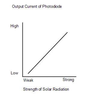
DTC Code

DTC Detection Condition

Trouble Area

B1421/21

Open or short in passenger side solar sensor circuit

  • Automatic light control sensor (solar sensor)
  • Harness and connector between solar sensor and air conditioning amplifier
  • Harness and connector between solar sensor and main body ECU
  • Main body ECU
  • Air conditioning amplifier

WIRING DIAGRAM

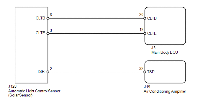
CAUTION / NOTICE / HINT

HINT:

If DTC B1244 is output at the same time, troubleshoot DTC B1244 first (see page ).

PROCEDURE

1.

READ VALUE USING TECHSTREAM (SOLAR SENSOR (for Passenger Side))

(a) Use the Data List to check if the passenger side solar sensor is functioning properly.

Air Conditioner

Tester Display

Measurement Item / Range

Normal Condition

Diagnostic Note

Solar Sensor (P Side)

Passenger side solar sensor /

Min.: 0

Max.: 255

Passenger side solar sensor voltage increases as brightness increases

Open in circuit: 0

Short in circuit: 255

OK:

The display is as specified in the normal condition.

Result

Result

Proceed to

NG

A

OK (Checking from the PROBLEM SYMPTOMS TABLE)

B

OK (Checking from the DTC)

C

B

PROCEED TO NEXT CIRCUIT INSPECTION SHOWN IN PROBLEM SYMPTOMS TABLE

C

REPLACE AIR CONDITIONING AMPLIFIER

A

2.

CHECK HARNESS AND CONNECTOR (SOLAR SENSOR)

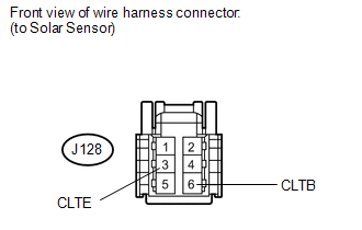
(a) Disconnect the J128 solar sensor connector.

(b) Measure the resistance according to the value(s) in the table below.

Standard resistance:

Tester Connection

Condition

Specified Condition

J128-3 (CLTE) - Body ground

Always

Below 1 Ω

(c) Measure the voltage according to the value(s) in the table below.

Standard voltage:

Tester Connection

Switch Condition

Specified Condition

J128-6 (CLTB) - J128-3 (CLTE)

Ignition switch ON

11 to 14 V

Ignition switch OFF

Below 1 V

NG

GO TO STEP 5

OK

3.

CHECK HARNESS AND CONNECTOR (AIR CONDITIONING AMPLIFIER - SOLAR SENSOR)

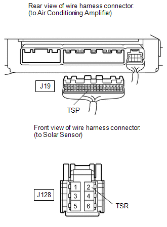
(a) Disconnect the J19 air conditioning amplifier connector.

(b) Disconnect the J128 solar sensor connector.

(c) Measure the resistance according to the value(s) in the table below.

Standard resistance:

Tester Connection

Condition

Specified Condition

J19-32 (TSP) - J128-2 (TSR)

Always

Below 1 Ω

J19-32 (TSP) or J128-2 (TSR) - Body ground

Always

10 kΩ or higher

NG

REPAIR OR REPLACE HARNESS OR CONNECTOR

OK

4.

CHECK AUTOMATIC LIGHT CONTROL SENSOR (SOLAR SENSOR (TSR - CLTE VOLTAGE))

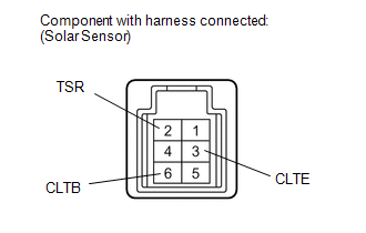
(a) Remove the solar sensor with its connector still connected (see page ).

(b) Apply battery voltage between terminals 6 (CLTB) and 3 (CLTE) of the solar sensor.

(c) Measure the voltage according to the value(s) in the table below.

Standard voltage:

Tester Connection

Condition

Specified Condition

2 (TSR) - 3 (CLTE)

Sensor is subjected to electric light

0.8 to 4.3 V

Sensor is covered with a cloth

Below 0.8 V

HINT:

  • As the inspection light is moved away from the sensor, the voltage decreases.
  • Use an incandescent light for inspection. Bring it approximately 30 cm (11.8 in.) from the solar sensor.
OK

REPLACE AIR CONDITIONING AMPLIFIER

NG

REPLACE AUTOMATIC LIGHT CONTROL SENSOR (SOLAR SENSOR)

5.

CHECK HARNESS AND CONNECTOR (MAIN BODY ECU - SOLAR SENSOR AND BODY GROUND)

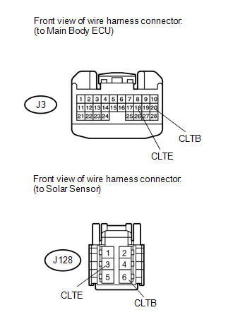
(a) Disconnect the J3 ECU connector.

(b) Disconnect the J128 solar sensor connector.

(c) Measure the resistance according to the value(s) in the table below.

Standard resistance:

Tester Connection

Condition

Specified Condition

J3-18 (CLTE) - J128-3 (CLTE)

Always

Below 1 Ω

J3-20 (CLTB) - J128-6 (CLTB)

J3-18 (CLTE) or J128-3 (CLTE) - Body ground

Always

10 kΩ or higher

J3-20 (CLTB) or J128-6 (CLTB) - Body ground

OK

REPLACE MAIN BODY ECU

NG

REPAIR OR REPLACE HARNESS OR CONNECTOR

    Evaporator Temperature Sensor Circuit (B1413/13)

    Compressor Lock Sensor Circuit (B1422/22)

    See More:

    Toyota Tundra Service Manual > Power Mirror Control System(w/ Memory): Operation Check
    OPERATION CHECK 1. CHECK MEMORY AND REACTIVATION FUNCTION HINT: The SET, M1 and M2 switches of the seat memory switch are shown in the illustration. (a) Turn the ignition switch ON and move the shift lever into the P position. (b) Check the M1 switch. (1) Using the mirror master switch and mirror co ...

    Toyota Tundra Owners Manual

    Toyota Tundra Service Manual

    © 2024 Copyright www.ttundra.com
    0.0333