DESCRIPTION This DTC is output when refrigerant pressure is extremely low (196 kPa (2.0 kgf/cm2, 28 psi) or less) or extremely high (3140 kPa (32.0 kgf/cm2, 455 psi) or more). The pressure switch, which is installed on the pipe of the high pressure side to detect refrigerant pressure, outputs a refrigerant pressure signal to the air conditioning amplifier. The air conditioning amplifier controls the compressor according to the sensor characteristic. HINT: Be sure to check the refrigerant volume first when this DTC is output because this DTC can also be output if there is no refrigerant in the system.
WIRING DIAGRAM 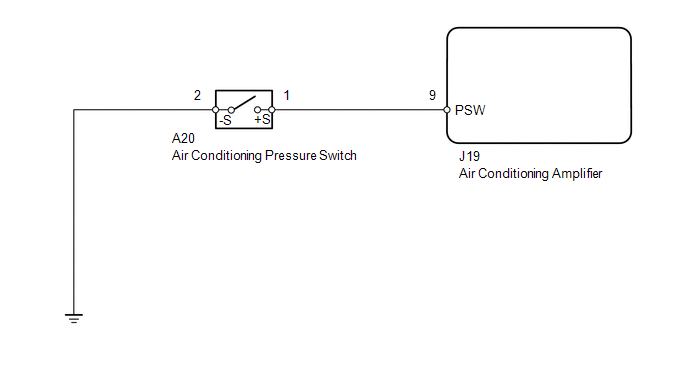
CAUTION / NOTICE / HINT HINT: Be sure to check the refrigerant volume first when this DTC is output because this DTC can also be output if there is no refrigerant in the system. PROCEDURE
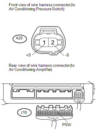
(a) Disconnect the A20 air conditioning pressure switch connector. (b) Disconnect the J19 air conditioning amplifier connector. (c) Measure the resistance according to the value(s) in the table below. Standard resistance:
(a) Set the manifold gauge set. 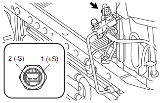
(b) Disconnect the A20 air conditioning pressure switch connector. (c) Run the engine at approximately 2000 rpm. (d) Set the blower speed control switch to the HI position. (e) Set the temperature control level to the MAX. COOL position. (f) Turn the A/C switch ON. (g) Check the switch operation. (1) Connect the positive (+) lead from an ohmmeter to terminal 1 (+S) and the negative (-) lead to terminal 2 (-S). (2) Measure the resistance between the terminals when refrigerant pressure is changed as shown in the illustration. 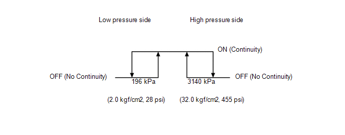
OK: Resistance varies as shown in the illustration. Result
|
Toyota Tundra Service Manual > Wiper / Washer: Washer Motor
Components COMPONENTS ILLUSTRATION Inspection INSPECTION PROCEDURE 1. INSPECT WINDSHIELD WASHER MOTOR AND PUMP ASSEMBLY HINT: This check should be performed with the windshield washer motor and pump installed to the washer jar. (a) Fill the washer jar with washer fluid. (b) Connect the battery's ...


