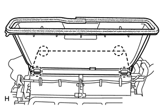
DISASSEMBLY PROCEDURE 1. REMOVE LOWER DEFROSTER NOZZLE ASSEMBLY
2. REMOVE NO. 1 AIR DUCT SUB-ASSEMBLY
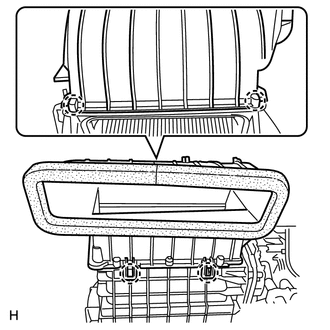
3. REMOVE AIR FILTER COVER PLATE
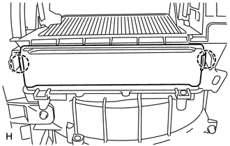
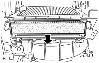
4. REMOVE CLEAN AIR FILTER
5. REMOVE NO. 3 AIR DUCT SUB-ASSEMBLY
6. REMOVE AIR CONDITIONING AMPLIFIER ASSEMBLY
7. REMOVE BLOWER WITH FAN MOTOR SUB-ASSEMBLY
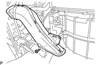
8. REMOVE AIR DUCT
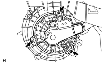
9. REMOVE NO. 1 DAMPER SERVO SUB-ASSEMBLY
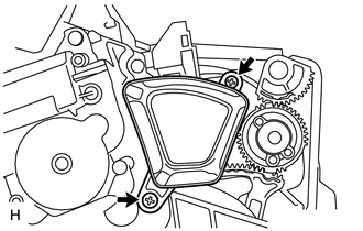
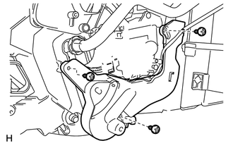
(b) Remove the 4 screws and No. 1 damper servo sub-assembly. 10. REMOVE DAMPER SERVO SUB-ASSEMBLY (for Automatic Air Conditioning System)
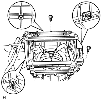
(b) Remove the 3 screws and damper servo sub-assembly. 11. REMOVE BLOWER UPPER CASE SUB-ASSEMBLY
(b) Detach the 2 claws and remove the blower upper case sub-assembly. 12. REMOVE BLOWER DAMPER SERVO SUB-ASSEMBLY
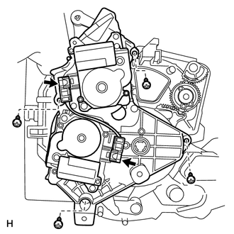
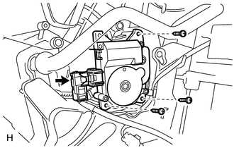
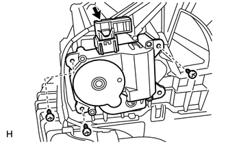
(b) Remove the 3 screws and blower damper servo sub-assembly. 13. REMOVE COOLING UNIT DAMPER SERVO SUB-ASSEMBLY (for Automatic Air Conditioning System) 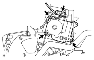
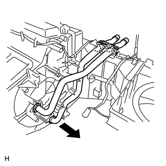
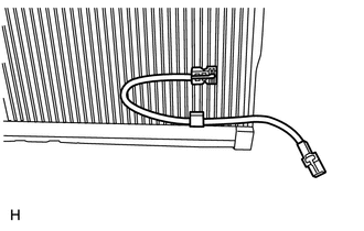
(a) Disconnect the connector. (b) Remove the 3 screws and cooling unit damper servo sub-assembly. 14. REMOVE HEATER RADIATOR UNIT SUB-ASSEMBLY
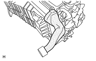
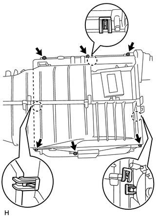
(c) Remove the heater radiator unit sub-assembly. 15. REMOVE NO. 1 COOLER EVAPORATOR SUB-ASSEMBLY
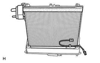
(c) Remove the blower case (back side).
16. REMOVE NO. 1 COOLER THERMISTOR
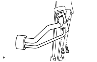
17. REMOVE COOLER EXPANSION VALVE
(b) Remove the tube and accessory and 2 O-rings. (c) Remove the cooler expansion valve and 2 O-rings from the No. 1 cooler evaporator sub-assembly. |
Toyota Tundra Service Manual > Airbag System: Short in P/T Squib (RH) Circuit (B1900-B1903)
DESCRIPTION The front pretensioner RH circuit consists of the airbag sensor assembly and front seat outer belt assembly RH. This circuit instructs the SRS to deploy when deployment conditions are met. These DTCs are stored when a malfunction is detected in the front pretensioner RH circuit. DTC No. ...