INSTALLATION PROCEDURE 1. INSTALL AIR CONDITIONING UNIT (a) Install the air conditioning unit with the nut. Torque: 5.4 N·m {55 kgf·cm, 48 in·lbf} 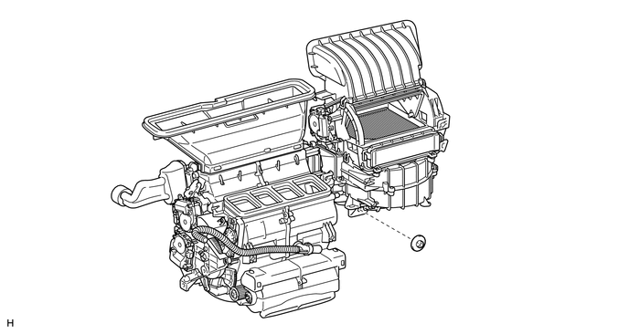
2. INSTALL REAR NO. 1 AIR DUCT (a) Attach the 7 claws to install the rear No. 1 air duct. 3. INSTALL REAR NO. 3 AIR DUCT (a) Attach the 7 claws to install the rear No. 3 air duct. 4. INSTALL INSTRUMENT PANEL REINFORCEMENT ASSEMBLY (a) Install the instrument panel reinforcement assembly. 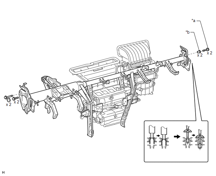
(1) Temporarily install the instrument panel reinforcement assembly. (2) for Passenger Side: Using a 12 mm hexagon wrench, install the 2 collars. (3) for Passenger Side: Using a T40 "TORX" socket, install the 2 "TORX" bolts. Torque: 18 N·m {184 kgf·cm, 13 ft·lbf} (4) for Driver Side: Install the 3 bolts and 2 caps. (b) Attach the clamps and connectors to connect the wire harness. (c) Install the 11 bolts and 4 nuts in the order shown in the illustration. Torque: Bolt A : 9.8 N·m {100 kgf·cm, 87 in·lbf} Bolt B : 8.4 N·m {86 kgf·cm, 74 in·lbf} Bolt C : 18 N·m {184 kgf·cm, 13 ft·lbf} 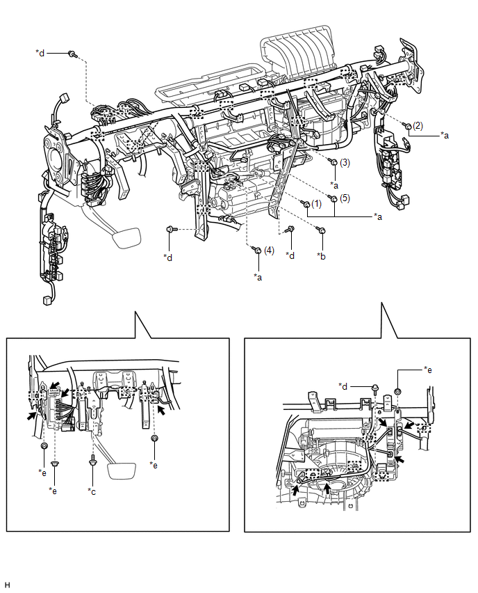
5. INSTALL INSTRUMENT PANEL SUB-ASSEMBLY (a) for Column Shift Type: Click here (b) for Floor Shift Type: Click here 6. INSTALL STEERING COLUMN ASSEMBLY Click here 7. INSTALL FRONT WIPER MOTOR AND BRACKET Click here 8. CONNECT INLET HEATER WATER HOSE AND OUTLET HEATER WATER HOSE
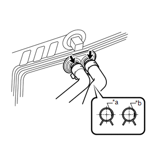
9. CONNECT SUCTION PIPE SUB-ASSEMBLY AND AIR CONDITIONER TUBE ASSEMBLY (for HFC-134a(R134a)) (a) Remove the attached vinyl tape from the tubes. (b) Sufficiently apply compressor oil to 2 new O-rings and the fitting surface of the suction pipe sub-assembly and air conditioner tube assembly. Compressor oil: ND-OIL 12 or equivalent (c) Install the 2 O-rings to the suction pipe sub-assembly and air conditioner tube assembly.
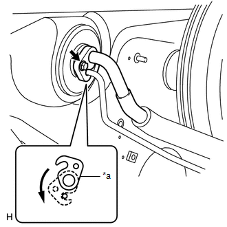
(e) Attach the plate as shown in the illustration and install the bolt. Torque: 9.8 N·m {100 kgf·cm, 87 in·lbf} 10. CONNECT AIR CONDITIONING TUBE ASSEMBLY (for HFO-1234yf(R1234yf)) (a) Remove the attached vinyl tape from the air conditioning tube assembly. (b) Sufficiently apply compressor oil to 2 new O-rings and the fitting surface of the air conditioning tube assembly. Compressor oil: ND-OIL 12 or equivalent (c) Install the 2 O-rings to the air conditioning tube assembly.
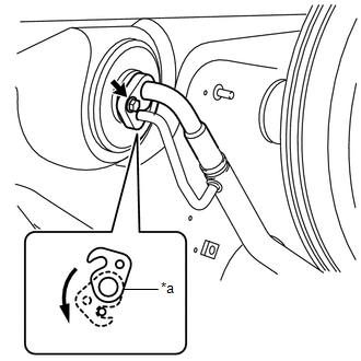
(e) Attach the plate as shown in the illustration and install the bolt. Torque: 9.8 N·m {100 kgf·cm, 87 in·lbf} 11. INSTALL NO. 2 COOLER COVER
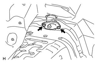
(b) Install the 2 nuts. Torque: 5.4 N·m {55 kgf·cm, 48 in·lbf} 12. CONNECT CABLE TO NEGATIVE BATTERY TERMINAL NOTICE: When disconnecting the cable, some systems need to be initialized after the cable is reconnected. Click here 13. PERFORM DIAGNOSTIC SYSTEM CHECK Click here 14. CHECK SRS WARNING LIGHT Click here 15. ADD ENGINE COOLANT (a) for 1UR-FE: Click here (b) for 3UR-FE: Click here (c) for 3UR-FBE: Click here 16. CHARGE REFRIGERANT (for HFC-134a(R134a)) Click here 17. CHARGE AIR CONDITIONING SYSTEM WITH REFRIGERANT (for HFO-1234yf(R1234yf)) Click here 18. WARM UP ENGINE (a) for HFC-134a(R134a): Click here (b) for HFO-1234yf(R1234yf): Click here 19. INSPECT FOR COOLANT LEAK (a) for 1UR-FE: Click here (b) for 3UR-FE: Click here (c) for 3UR-FBE: Click here 20. CHECK FOR REFRIGERANT GAS LEAK (for HFC-134a(R134a)) Click here 21. INSPECT FOR REFRIGERANT LEAK (for HFO-1234yf(R1234yf)) Click here |
Toyota Tundra Owners Manual > Toyota Tundra Owners Manual: For your information
Main Owner's Manual Please note that this manual applies to all models and all equipment, including options. Therefore, you may find some explanations for equipment not installed on your vehicle. All specifications provided in this manual are current at the time of printing. However, because of the ...