REASSEMBLY PROCEDURE 1. INSTALL COOLER EXPANSION VALVE
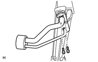
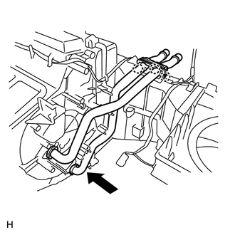
(b) Install the 2 O-rings to the No. 1 cooler evaporator sub-assembly. (c) Install the 2 O-rings to the tube and accessory. (d) Install the cooler expansion valve and tube and accessory to the No. 1 cooler evaporator sub-assembly. (e) Using a 4 mm hexagon wrench, install the 2 bolts. Torque: 3.5 N·m {36 kgf·cm, 31 in·lbf} 2. INSTALL NO. 1 COOLER THERMISTOR
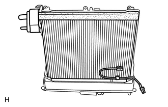
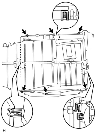
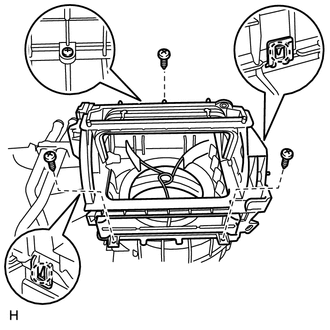
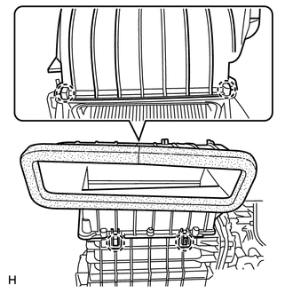
3. INSTALL NO. 1 COOLER EVAPORATOR SUB-ASSEMBLY
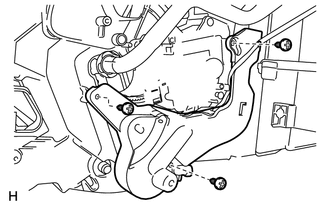
(c) Install the 6 screws and attach the 3 claws.
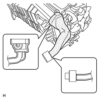
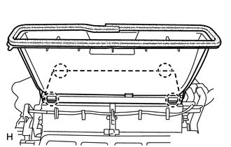
4. INSTALL HEATER RADIATOR UNIT SUB-ASSEMBLY
(b) Attach the 3 claws to install the heater clamp.
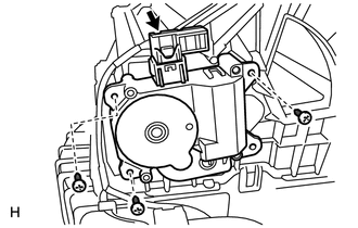
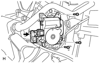
5. INSTALL COOLING UNIT DAMPER SERVO SUB-ASSEMBLY (for Automatic Air Conditioning System)
(b) Connect the connector. 6. INSTALL BLOWER DAMPER SERVO SUB-ASSEMBLY
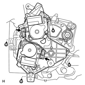
(b) Connect the connector. 7. INSTALL BLOWER UPPER CASE SUB-ASSEMBLY
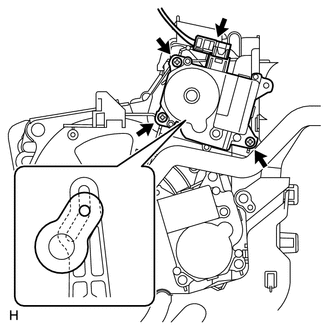
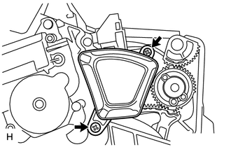
(b) Install the 3 screws. 8. INSTALL DAMPER SERVO SUB-ASSEMBLY (for Automatic Air Conditioning System)
(b) Connect the connector. 9. INSTALL NO. 1 DAMPER SERVO SUB-ASSEMBLY (a) Set the No. 1 damper servo sub-assembly so that the cutout part engages with the tooth of the gear, and attach the claw to install the No. 1 damper servo sub-assembly. 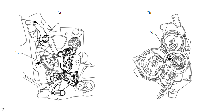
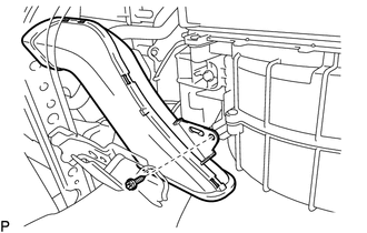
10. INSTALL AIR DUCT
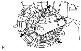
11. INSTALL BLOWER WITH FAN MOTOR SUB-ASSEMBLY
12. INSTALL AIR CONDITIONING AMPLIFIER ASSEMBLY
13. INSTALL NO. 3 AIR DUCT SUB-ASSEMBLY
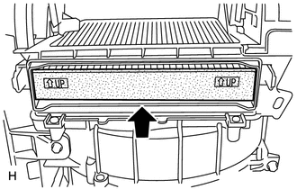
14. INSTALL CLEAN AIR FILTER
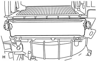
15. INSTALL AIR FILTER COVER PLATE
16. INSTALL NO. 1 AIR DUCT SUB-ASSEMBLY
17. INSTALL LOWER DEFROSTER NOZZLE ASSEMBLY
|
Toyota Tundra Service Manual > Trailer Brake Control System: Stop Light Control Relay Malfunction (C1380)
DESCRIPTION The skid control ECU (brake actuator assembly) sends a stop light operation request signal to the stop light control relay. If the skid control ECU (brake actuator assembly) detects a malfunction in the stop light control relay circuit, the trailer brake control ECU (brake control with b ...